Very small aperture terminal with dual-input DC power control

a technology of power control and small aperture, applied in pulse shaping, pulse automatic control, substation equipment, etc., can solve the problem of requiring considerable power to enable radio transmission

Active Publication Date: 2005-08-11
WISTRON NEWEB
View PDF7 Cites 2 Cited by
  • Summary
  • Abstract
  • Description
  • Claims
  • Application Information

AI Technical Summary

Benefits of technology

[0016] The first transistor is a P-channel metal-oxide semiconductor field effect transistor and the second transistor is an N-channel field effect transistor or a NPN bipolar transistor.

Problems solved by technology

Although signal transfer systems in electronic circuits are minimized, considerable power is required to enable radio transmission.

Method used


Image

  • Very small aperture terminal with dual-input DC power control
  • Very small aperture terminal with dual-input DC power control
  • Very small aperture terminal with dual-input DC power control

Examples


Embodiment Construction

[0022] A detailed description of the present invention is provided in the following.

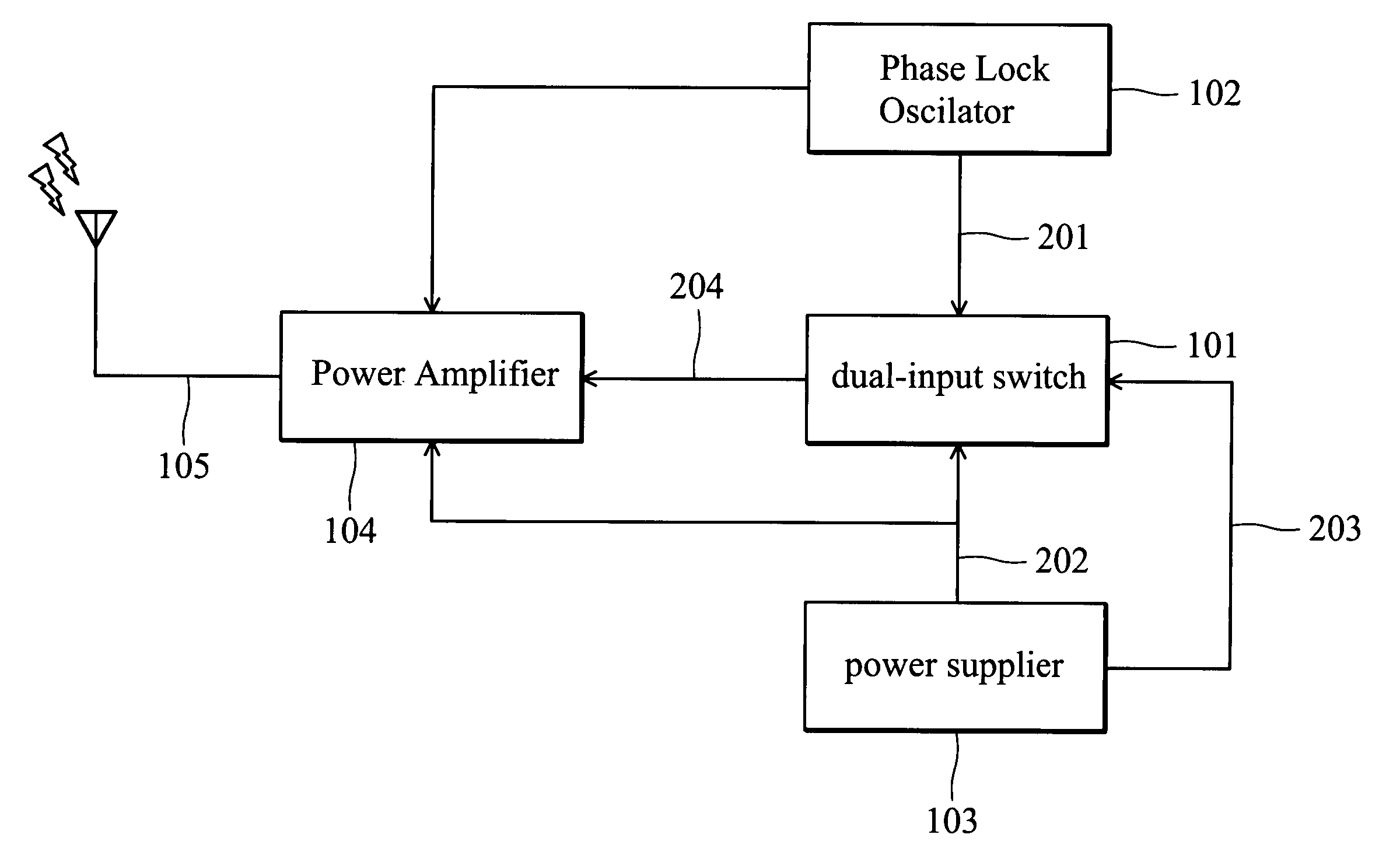
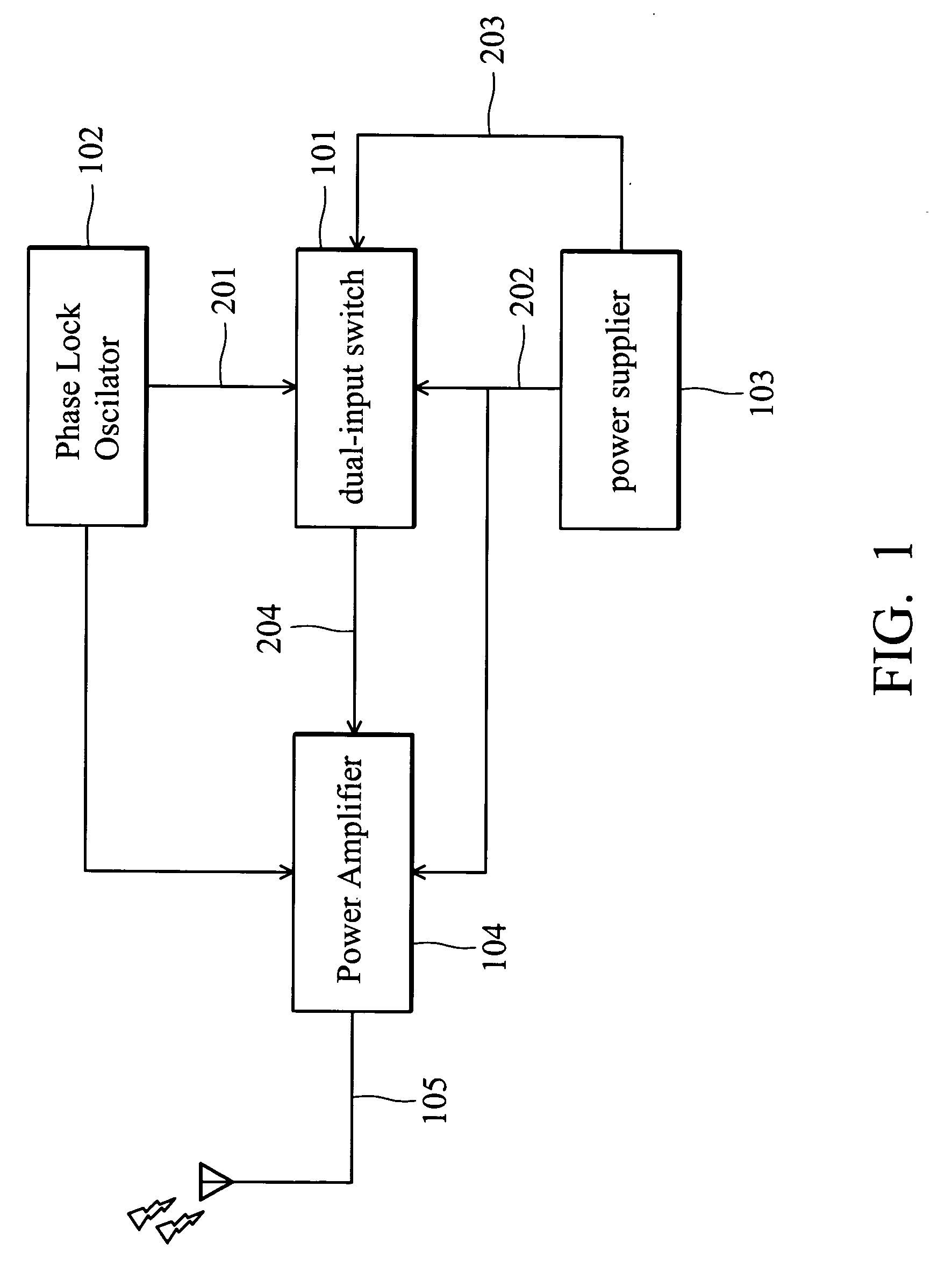
[0023]FIG. 1 shows an embodiment of the dual-input switch 101, for controlling conductance of the circuit according the present invention. A stable high frequency signal is generated from an unstable low frequency signal by a PLO 102, and input to a power amplifier 104 for VSAT communication. In the power amplifier 104, a protection circuit driven by negative power supplied by the power supply 103 is provided. Additionally, the power supply 103 simultaneously provides a first power potential for the switch 101 through a first power node 202. The switch 101 is connected to the power supply 103 through an input node 203, and is connected to the power amplifier 104 through an output node 204. The status of the PLO 102 and power supply 103 determine the conductance of the input node 203 and the output node 204. The PLO 102 comprises a locking node 201. The power supply 103 comprises a first power node 2...


PUM


Abstract

The present invention relates to a satellite signal transmitter, and in particular, to a satellite signal transmitter with a dual-input DC power control switch.

Description

BACKGROUND OF THE INVENTION [0001] 1. Field of the Invention [0002] The present invention relates to a very small aperture terminal (VSAT), and in particular, to a VSAT with a dual-input DC power control. [0003] 2. Description of the Related Art [0004] A VSAT satellite communicator transmits and receives signals through a mini-antenna, transferring video and audio information through high bandwidth connections provided within range of the satellite signal. Currently satellite networking services are highly developed so that various application services are popular. Portable satellite communication devices are widely used, with the result that low power consumption is a priority. [0005] Although signal transfer systems in electronic circuits are minimized, considerable power is required to enable radio transmission. Thus a power amplifier provides amplification necessary for the minimized circuits to provide radio waves of sufficient power. [0006] The power amplifier magnifies an inp...

Claims


Application Information

Patent Timeline
Patent Type & Authority Applications(United States)
IPC IPC(8): H01Q11/12H03K5/08H03L5/00H04B1/02H04B1/04
CPCH04B1/0466
Inventor HUANG, CHUANG-CHIA
Owner WISTRON NEWEB
Why Eureka
Try Eureka