Transparent measuring device with enhanced visibility lines

a technology of transparency and visibility lines, applied in the direction of mechanical measuring arrangements, instruments, printing, etc., can solve the problems of opaque lines blocking the view of the material under, the complex nature of the manufacturing process, and the application of multiple images to the transparent base, etc., and achieve the effect of enhanced visibility lines

Inactive Publication Date: 2005-08-18
RULERSMITH IP
View PDF12 Cites 14 Cited by
  • Summary
  • Abstract
  • Description
  • Claims
  • Application Information

AI Technical Summary

Benefits of technology

[0010] The disclosed embodiments of the invention are directed to a transparent measuring device having enhanced visibility lines. In one embodiment, a tool for measuring and marking material and guiding a hand-held rotary cutting tool is provided. The tool includes a transparent substrate having mutually-opposing planar front and back surfaces, the substrate formed to have a thickness that is adapted to guide the hand-held rotary cutting tool; a first set of gridlines formed on at least one of the front and back surfaces of the transparent substrate, the first set of gridlines formed to be opaque; and a second set of gridlines formed on at least one of the front and back surfaces of the transparent substrate, the second set of gridlines formed to have a width greater than a width of the first set of gridlines and positioned to at least partially overlap the first set of gridlines, the second set of gridlines formed to be transparent and of a contrasting color to the first set of gridlines to highlight the first set of gridlines and to enable viewing of material on which the tool is placed.

Problems solved by technology

The disadvantages of the prior methods include the complex nature of the manufacturing process, that is, the forming of multiple images and the application of the images to the transparent base.
Another disadvantage is that the opaque lines block the view of the material thereunder.
In addition, these lines are difficult to see in low-light situations.

Method used


Image

  • Transparent measuring device with enhanced visibility lines
  • Transparent measuring device with enhanced visibility lines
  • Transparent measuring device with enhanced visibility lines

Examples


Embodiment Construction

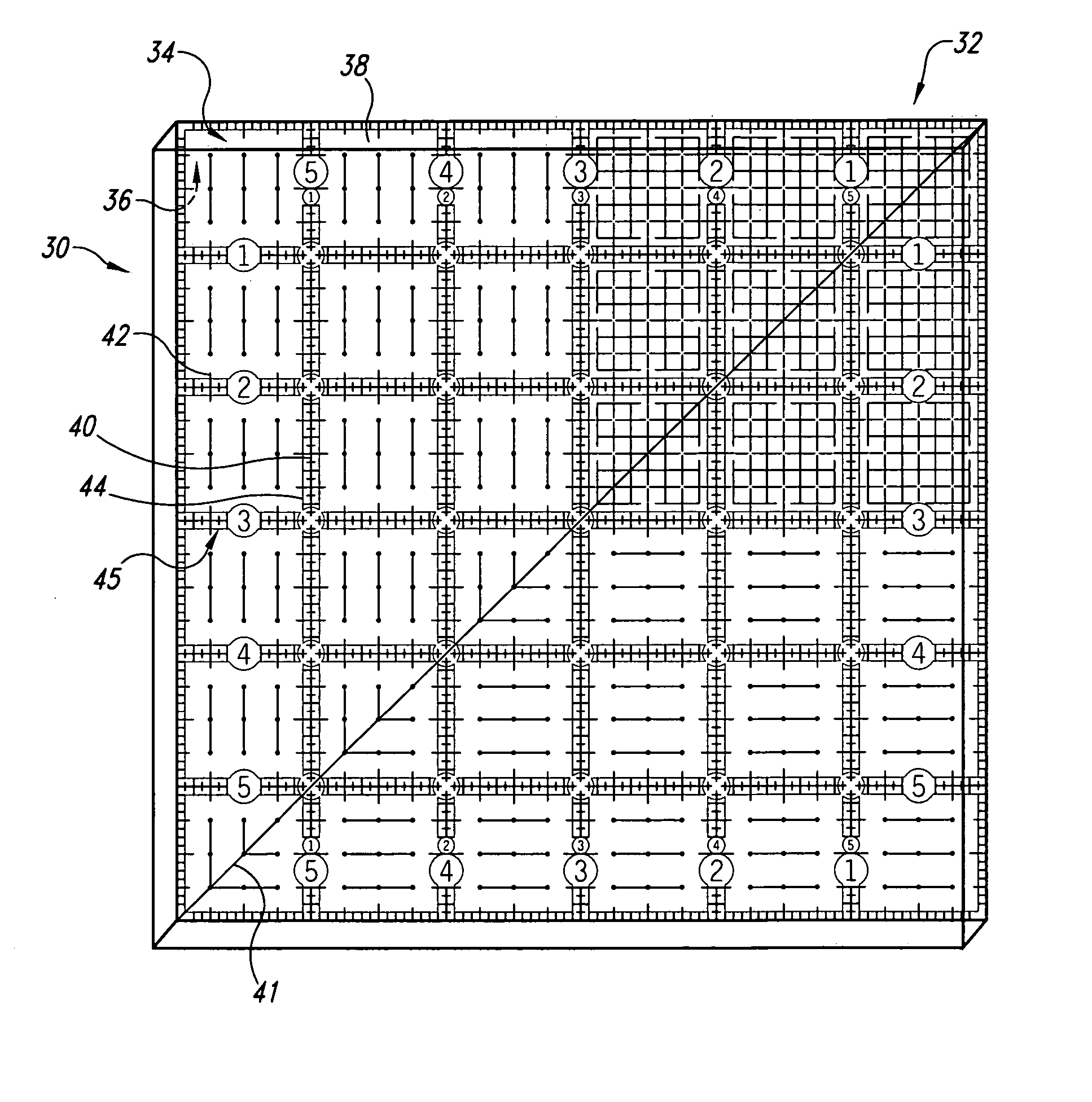
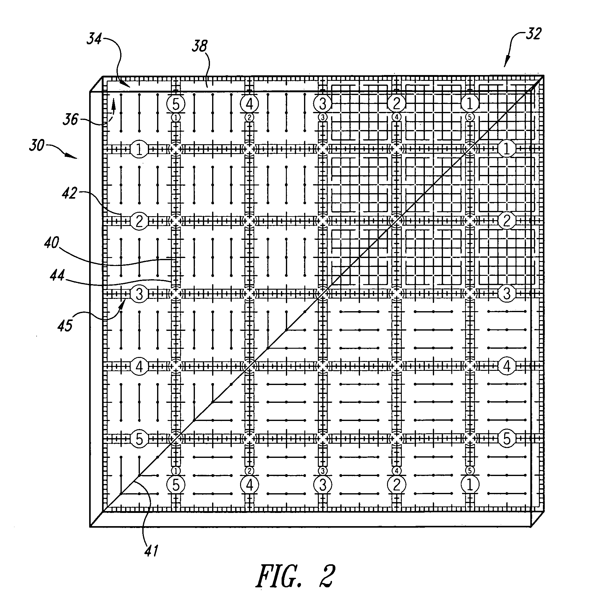
[0026] Referring initially to FIG. 2, an improved transparent measuring device 30 is shown therein for use in measuring, marking, and cutting material. The device 30 is formed from a sheet 32 of transparent material having planar opposing front and back surfaces 34, 36 respectively. Ideally the sheet 32 of transparent material is formed of clear acrylic. However, other clear, rigid material that accepts ink or that accepts flexible material adhered by surface adhesion, static cling, or adhesive may be used.

[0027] In one embodiment, the sheet 32 of transparent material is sufficiently thick to form a sidewall 38 to guide a cutting tool, such as a hand-held rotary cutting tool, scissors, knife, and the like, or a marking tool.

[0028] At least one and preferably a plurality of opaque ruled lines 40 having marked graduations 42 are formed on the sheet 32, preferably on the back surface 36 to reduce parallax error. Ideally the plurality of opaque lines 40 are printed on the transparent ...


PUM


Abstract

A transparent measuring device with enhanced visibility lines formed on a transparent substrate having opposing planar front and back surfaces and with at least one opaque line formed on one of the front and back surfaces and at least one transparent line formed on one of the front and back surfaces to be colinear with the at least one opaque line to present a composite line where the transparent line permits viewing of material on which the device is placed while highlighting the at least one opaque line for enhanced visibility. The transparent line may be formed of excitable pigment that reacts to light, such as a black light, or that retains luminance after exposure to light.

Description

CROSS-REFERENCE TO RELATED APPLICATION [0001] This application is a continuation-in-part of U.S. patent application Ser. No. 10 / 623,126, filed Jul. 17, 2003, now pending, which application is incorporated herein by reference in its entirety.BACKGROUND OF THE INVENTION [0002] 1. Field of the Invention [0003] The present invention pertains to a device for use in measuring, marking, and cutting material, and more particularly, to a transparent ruler having composite lines formed of an opaque line and a coincident translucent line of a greater width and of a contrasting color that is configured to enhance the visibility of the composite lines. [0004] 2. Description of the Related Art [0005] Transparent rulers having grid lines formed thereon are used for measuring and marking material, such as fabric, paper, plastic, and the like. These rulers are also used to guide a tool, such as a razor, knife, or rotary cutter in cutting the material to desired sizes and shapes. [0006] One such rule...

Claims


Application Information

Patent Timeline
Patent Type & Authority Applications(United States)
IPC IPC(8): B43L7/00G01D21/00G03B27/42
CPCB26B29/06B43L7/027B43L7/00
Inventor SCHAFER, RANDAL D.SCHAFER, MARGARET
Owner RULERSMITH IP
Why Eureka
Try Eureka