Power or manually operated pipe grooving tool

a technology of power or manual operation, applied in the field of tools, can solve problems such as inability to always have electric power

Active Publication Date: 2005-08-18
VICTAULIC
View PDF42 Cites 19 Cited by
  • Summary
  • Abstract
  • Description
  • Claims
  • Application Information

AI Technical Summary

Problems solved by technology

However, electrical power is not always available, especially at remote sites in the field.

Method used


Image

  • Power or manually operated pipe grooving tool
  • Power or manually operated pipe grooving tool
  • Power or manually operated pipe grooving tool

Examples


Embodiment Construction

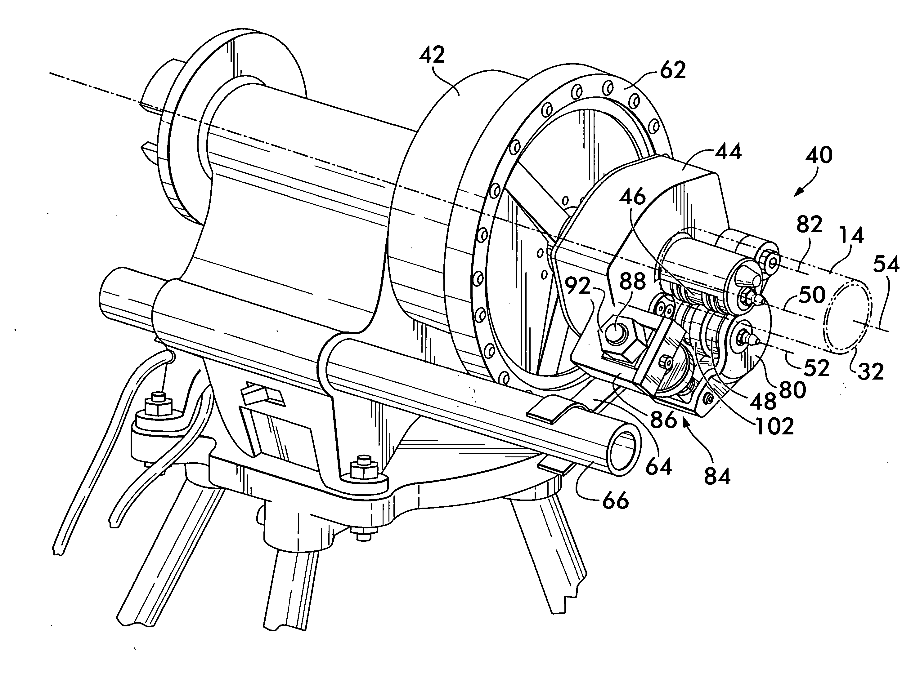
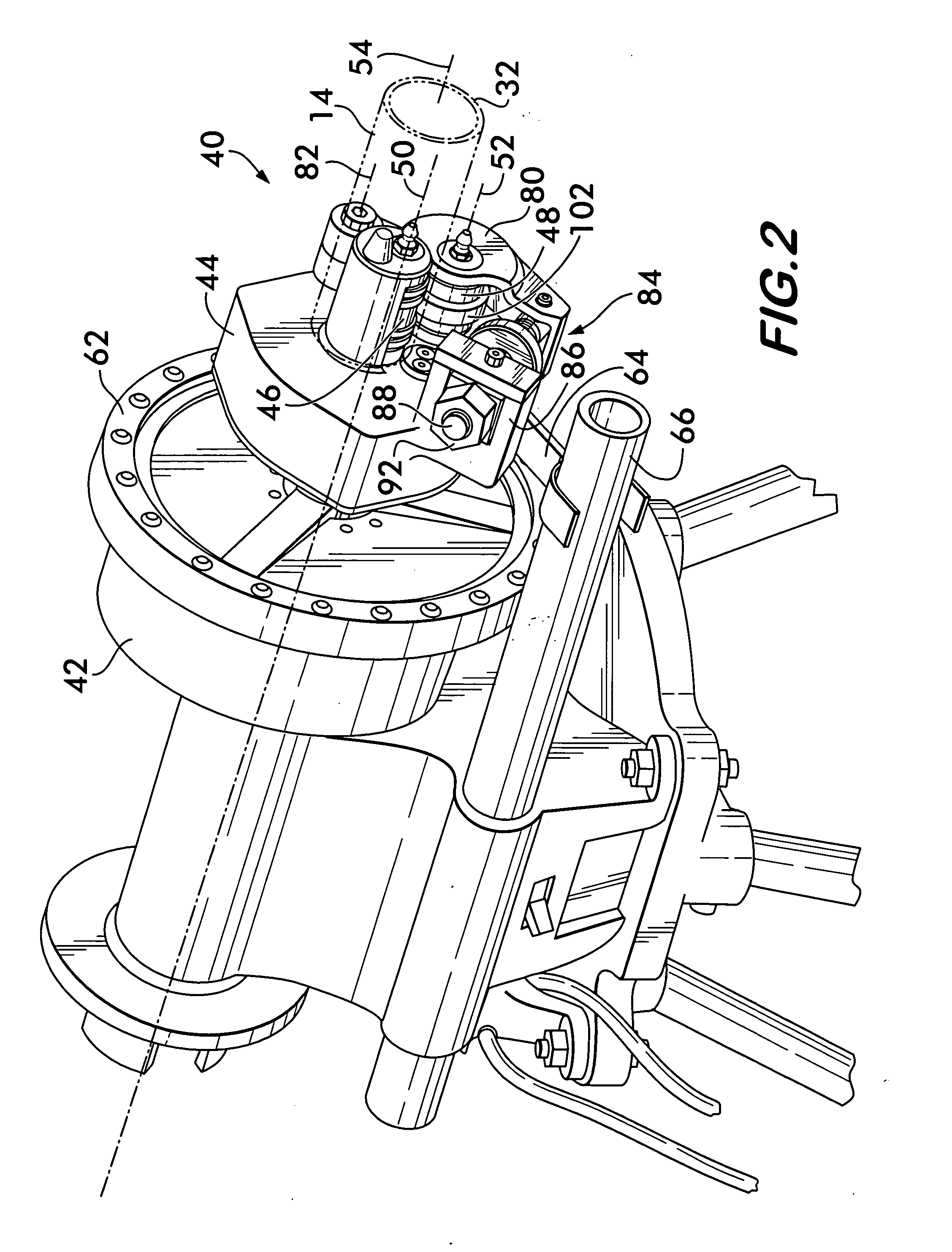
[0021]FIG. 2 shows a grooving tool 40 according to the invention removably mounted on a power drive unit 42 for power operation. Grooving tool 40 comprises a housing 44 on which are mounted a back-up roller 46 and a grooving roller 48, positioned adjacent to the back-up roller. The back-up roller 46 is rotatable about an axis 50, and the grooving roller 48 is rotatable about an axis 52. Both axes of rotation 50 and 52 are preferably substantially parallel to one another and to the longitudinal axis 54 of pipe 14, shown in phantom line with its sidewall 32 positioned between the rollers 46 and 48 for formation of a circumferential groove. It is also feasible to skew the axes relatively to one another and the pipe axis 54 by a few degrees to help ensure that the grooving tool tracks along the same path around the pipe.

[0022] Preferably, as shown in FIG. 6, back-up roller 46 is attached to a power drive shaft 56 rotatably mounted on housing 44. Power drive shaft 56 directly turns the ...


PUM

PropertyMeasurementUnit
transmissionaaaaaaaaaa
pitch diameteraaaaaaaaaa
internal pressureaaaaaaaaaa

Abstract

A pipe grooving tool is disclosed having a housing on which a back-up roller and a grooving roller are rotatably mounted. The grooving roller is pivotably movable toward the back-up roller and has a raised tool surface engageable with the outer surface of the pipe. The pipe is positioned with its sidewall between the rollers, and the back-up roller is rotated while the grooving roller is forcibly moved toward the back-up roller. A circumferential groove is formed around the pipe as the rollers traverse its circumference. A power drive shaft connected directly to the back-up roller is provided, the power drive shaft engaging a power drive unit on which the tool is mounted operated under power. A manual drive shaft is connected to the back-up roller through a torque multiplying gear and pinion transmission for manual operation of the tool.

Description

FIELD OF THE INVENTION [0001] This invention relates to tools that create circumferential grooves in pipes to allow the pipes to be connected together end to end using mechanical couplings. BACKGROUND OF THE INVENTION [0002] Mechanical couplings 10, as shown in FIG. 1, are used to couple pipes 12 and 14 to one another and effect a fluid tight joint. Couplings 10 may comprise a pair of segments 16 and 18 that are joined to one another end to end by fasteners 20 to circumferentially surround the ends of pipes 12 and 14. To effect a substantially rigid joint, i.e., a joint which resists relative rotation of the pipes 12 and 14 about their longitudinal axes, resists axial motion of the pipes relatively to one another due to internal pressure, and resist angular deflection of the pipes relatively to one another, it is advantageous to position circumferentially extending grooves 22 and 24 around each pipe. The grooves 22 and 24 are positioned in spaced relation to the ends of the pipes 12...

Claims


Application Information

Patent Timeline
Patent Type & Authority Applications(United States)
IPC IPC(8): B21D17/04
CPCB21D17/04
Inventor DOLE, DOUGLAS R.
Owner VICTAULIC
Why Eureka
Try Eureka