
Burn-in test apparatus for BGA packages using forced heat exhaust

a test apparatus and heat exhaust technology, applied in semiconductor/solid-state device testing/measurement, fault location by increasing destruction at fault, etc., can solve problems such as difficult to reliably control the temperature of the bga package, many such defective packages break down, and defects in semiconductor chip packages containing integrated circuit chips

Inactive Publication Date: 2005-08-18
SAMSUNG ELECTRONICS CO LTD
View PDF3 Cites 58 Cited by
  • Summary
  • Abstract
  • Description
  • Claims
  • Application Information

AI Technical Summary

Benefits of technology

The present invention is a better way to test the quality of ball grid array (BGA) packages. It includes a chamber with sockets that have air vents and contact pins to allow air to flow near the solder balls on the package. The sockets also have a recessed part to help with air circulation. The invention also has a duct to direct heated air from a heating unit to the chamber and another duct to direct air to the air supply tubes. Overall, this invention helps to better simulate the conditions under which BGA packages are used in real-life situations.

Problems solved by technology

Semiconductor chip packages containing integrated circuit chips may have defects which appear some time after fabrication or assembly.
Many such defective packages break down within approximately one thousand hours after use.
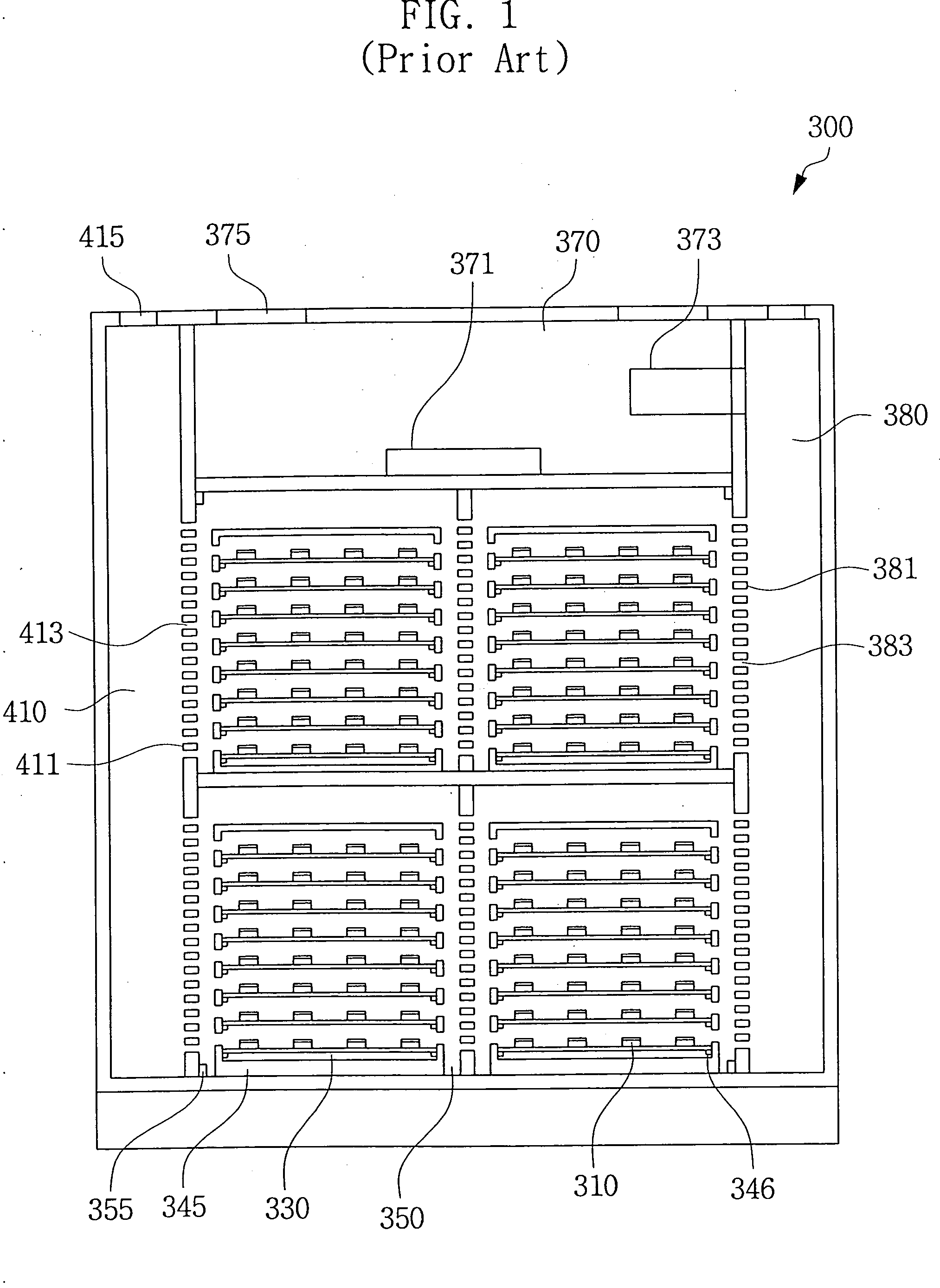
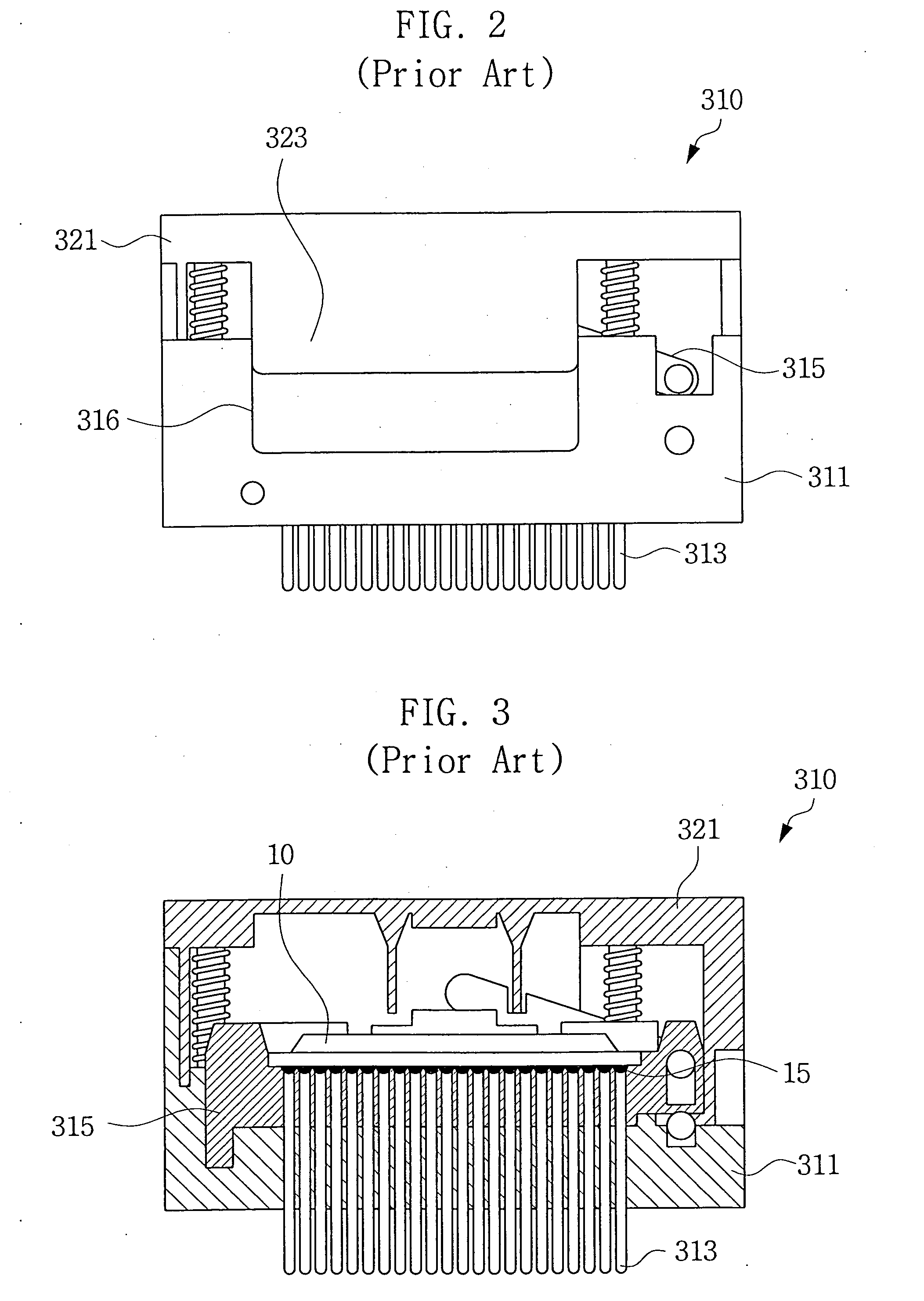
It is therefore difficult to reliably control the temperature of the BGA package 10 contained in each test socket 310.
Thus, the temperature inside the test socket 310 may exceed the melting point of solder, and this may lead to melting of the solder balls 15.
This may become a serious issue for advanced, highly-integrated and smaller packages.
In addition, the ball-melting problem may give rise to problems with the test socket 310, increasing repair expenses and lowering productivity.
The ball-melting problem may become a bottleneck in the development of new products.

Method used


Image

  • Burn-in test apparatus for BGA packages using forced heat exhaust
  • Burn-in test apparatus for BGA packages using forced heat exhaust
  • Burn-in test apparatus for BGA packages using forced heat exhaust

Examples


Embodiment Construction

[0030] Exemplary, non-limiting embodiments of the present invention will now be described with reference to the accompanying drawings. This invention may, however, be embodied in many different forms and the scope of this invention should not be construed as limited to the exemplary embodiments set forth herein. Rather, the disclosed embodiments are provided so that this disclosure will convey the scope of the invention to those skilled in the art. The principles and feature of this invention may be employed in varied and numerous embodiments without departing from the spirit and scope of the invention.

[0031] In the description, well-known structures and processes have not been described or illustrated in detail. It should be understood that the figures are not drawn to scale. Rather, for simplicity and clarity of illustration, the dimensions of some of the elements are exaggerated relative to other elements. Like reference numerals and characters are used for like and correspondin...


PUM


Abstract

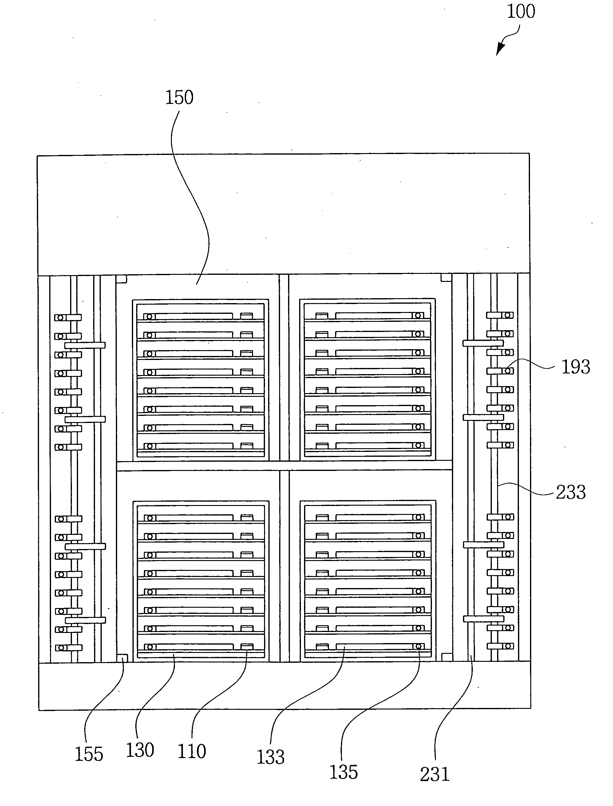
A forced air heat exhaust type of burn-in test apparatus for packages: A first air supply duct provides air to the burn-in chamber and a second air supply duct provides air to supply tubes that direst air into the test sockets that hold the packages. The test sockets have a structure that allows air ventilation of the conductive balls. Accordingly, the apparatus can control the temperature around the packages as well as the temperature in the burn-in chamber, thus preventing conductive ball-melting.

Description

CROSS REFERENCE TO RELATED APPLICATIONS [0001] This U.S. non-provisional application claims priority under 35 U.S.C. §119 to Korean Patent Application No. 2004-10375 filed Feb. 17, 2004. The entire content of Korean Patent Application No. 2004-10375 is hereby incorporated herein by reference. BACKGROUND OF THE INVENTION [0002] 1. Field of the Invention [0003] The present invention relates to a test apparatus used for semiconductor chip packages and, more particularly, to a burn-in test apparatus used for ball grid array (BGA) packages. [0004] 2. Description of the Related Art [0005] Semiconductor chip packages containing integrated circuit chips may have defects which appear some time after fabrication or assembly. Many such defective packages break down within approximately one thousand hours after use. For this reason, semiconductor chip packages are often subjected to a burn-in test before sale. In the burn-in test, the packages undergo extreme electrical and thermal stress for a...

Claims


Application Information

Patent Timeline
Patent Type & Authority Applications(United States)
IPC IPC(8): G01R1/04H01L21/66G01R31/02G01R31/28
CPCG01R1/0483G01R31/286G01R31/2879G01R31/2877G01R31/2862H05B3/44H05B3/14H05B3/03H05B2214/04
Inventor MIN, BYUNG-JUNKIM, WOO-JINBANG, JEONG-HOSHIM, HYUN-SEOPIY, HYUN-GEUNLEE, JAE-IL
Owner SAMSUNG ELECTRONICS CO LTD
Learn More