Tape printing apparatus and tape printing method

a printing apparatus and tape technology, applied in the direction of identification means, instruments, seals, etc., can solve the problems of not being able to form laminated labels, the print face is not fully laminated or printed, and the printing apparatus cannot be used to print labels. , to achieve the effect of fine adjustment of the tape width of the folded print tape, and reducing the width of the folded tap

Active Publication Date: 2005-08-18
SEIKO EPSON CORP
View PDF2 Cites 14 Cited by
  • Summary
  • Abstract
  • Description
  • Claims
  • Application Information

AI Technical Summary

Benefits of technology

[0008] According to one aspect of the present invention, there is provided a tape printing apparatus for performing printing on a print tape which includes: a recording tape layer formed of a print recording piece in one substantially half-part whose front face serves as a recording face and of a separating piece in the other substantially half-part, both of which are divided by a front cut-line formed at an intermediate position in a tape-width direction; and a transparent pseudo-laminate layer affixed to a rear face of the recording tape layer and having a laminating adhesive layer on a front-face side thereof and a transparent tape layer on a rear-face side thereof, wherein the separating-piece side of the pseudo-laminate layer is allowed to serve as a laminate tape for the recording face when folded and affixed to the front face of the print recording piece after separation of the separating piece. The tape printing apparatus comprises: an inputting means for inputting a character to be printed on the recording face; a folding-line defining means for defining a folding-line position of the pseudo-laminate layer; a width-range defining means for defining a print-width range of the recording face based on the defined folding-line position; and a printing means for printing the character in the defined print-width range.
[0009] According to another aspect of the present invention, there is provided a tape printing method in a tape printing apparatus for performing printing on a print tape which includes: a recording tape layer formed of a print recording piece in one substantially half-part whose front face serves as a recording face and of a separating piece in the other substantially half-part, both of which are divided by a front cut-line formed at an intermediate position in a tape-width direction; and a transparent pseudo-laminate layer affixed to a rear face of the recording tape layer and having a laminating adhesive layer on a front-face side thereof and a transparent tape layer on a rear-face side thereof, wherein the separating-piece side of the pseudo-laminate layer is allowed to serve as a laminate tape for the recording face when folded and affixed to the front face of the print recording piece after separation of the separating piece. The tape printing method comprises: an inputting step of inputting a character to be printed on the recording face; a folding-line defining step of defining a folding-line position of the pseudo-laminate layer; a width-range defining step of defining a print-width range of the recording face based on the defined folding-line

Problems solved by technology

The tape printing apparatus in the former case, however, does not enable to form laminated labels even with a tape cartridge additionally accommodating a laminate tape being inserted thereto, since the apparatus has no mechanism of bonding a print tape and a la

Method used


Image

  • Tape printing apparatus and tape printing method
  • Tape printing apparatus and tape printing method
  • Tape printing apparatus and tape printing method

Examples


first embodiment

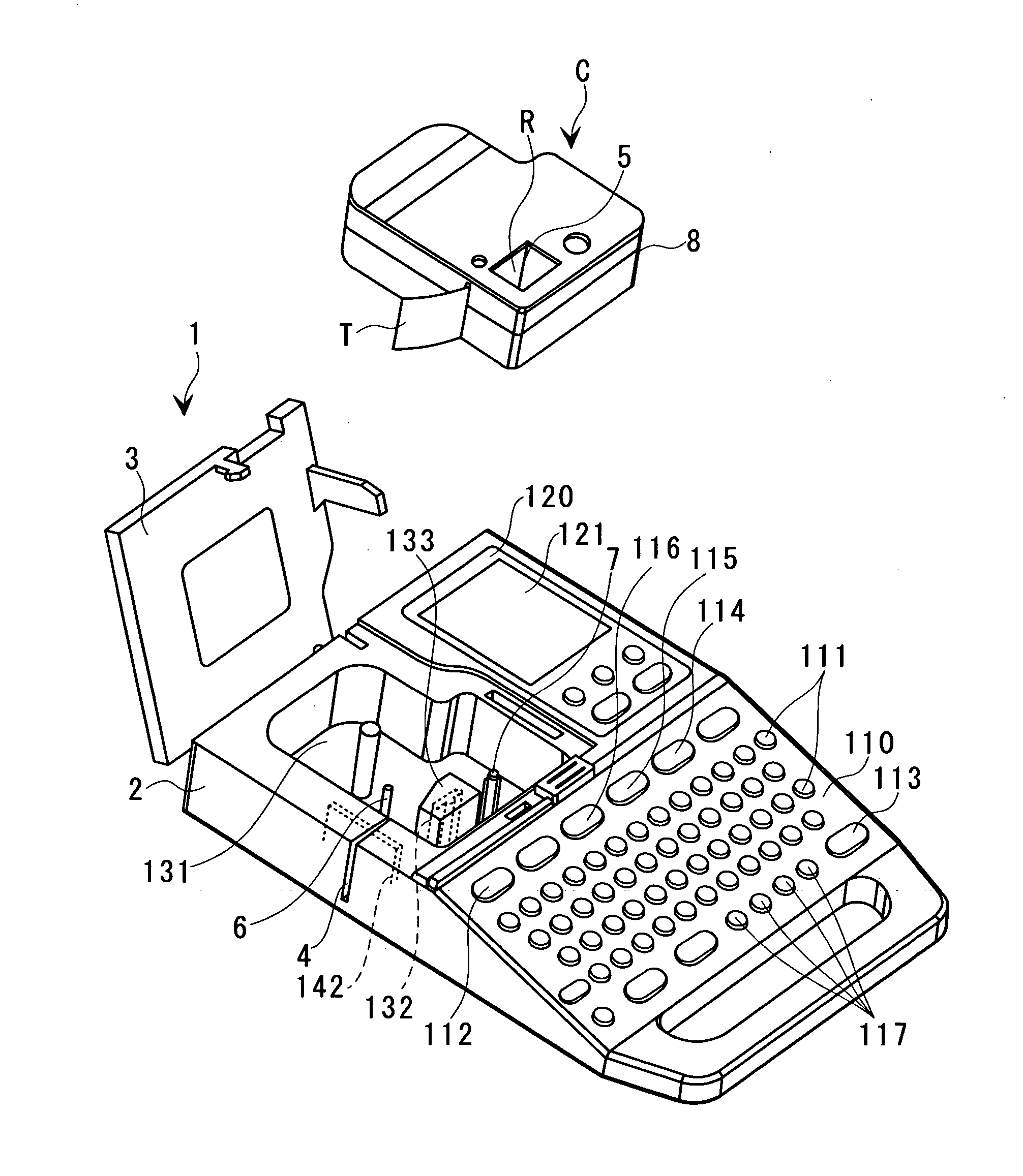
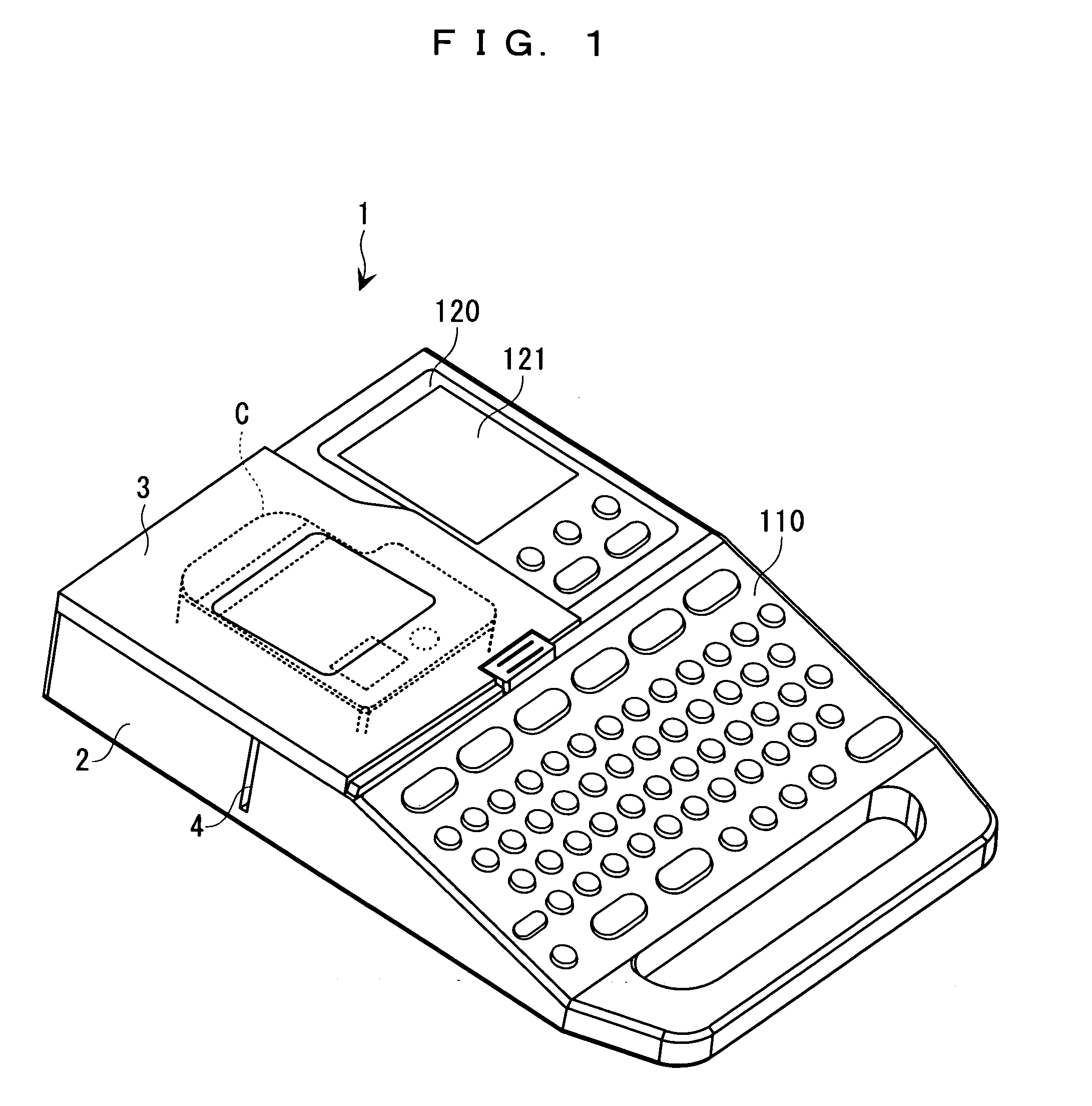
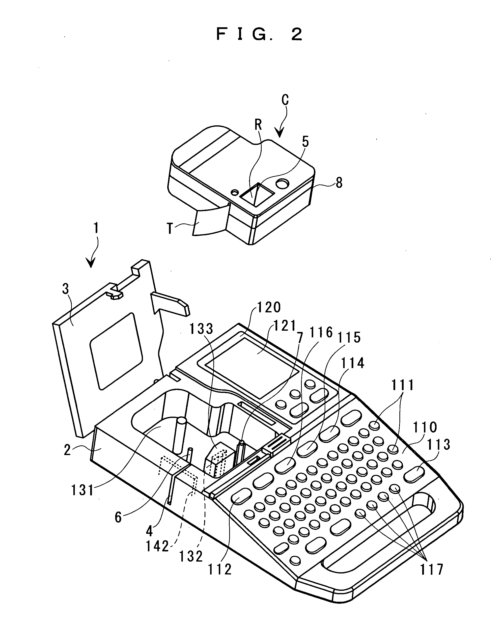
[0068] First, description of the first embodiment in which the insufficient folding is performed will be made with reference to FIG. 7. On the initial screen for laminate printing as described above, if the user operates the cursor “↓” key 117, displays the “7 mm label” in reverse video (T12), and presses the select key 113, a character-input screen (T13) appears.

[0069] The tape printing apparatus 1 defines not only a folding-line position B (see FIG. 9A) but also a print-width range P (also see FIG. 9A) on the recording face which will be specifically described below, provided that the tape width of a folded tape is the “7 mm label.” An input guide (the segment of “FIRST LINE [” displayed on the character-input screen (T13) indicates only the number of rows to which characters can be inputted based on the defined print-width range P.

[0070] On the character-input screen displayed, characters of “ABCDE” are then inputted (T14). Note that if the character-mode key 115 (see FIG. 2) or...

second embodiment

[0081] Next, flow of folding involving the rear-face wind folding will be described below with reference to FIGS. 11A to 11E. A label R in each of the figures refers to a label cut into a desired length in which the characters of “ABCDE” and the auxiliary line as described in the second embodiment are printed on the recording face of the recording tape layer 10 of the tape T.

[0082] In the second embodiment, since the tape width of the folded tape is set to 5 mm, the folding-line position B is set at a distance of 7 mm from the folding end 10a of the recording tape layer 10, and the folding-line L is printed at a distance of 7 mm from the folding end 10a of the recording tape layer 10 of the tape T (FIG. 11A).

[0083] First, part of the separating piece 12 or the print recording piece 11 of the recording tape layer 10 is folded along the folding-line L to make a habitual folding line thereat (FIG. 11B). Next, the folded label R is restored to an initial state, and substantially the ha...


PUM


Abstract

There is provided a tape printing apparatus in which characters to be printed on a recording face of a recording tape layer of a print tape are inputted, and a folding-line position of a pseudo-laminate layer of the print tape is defined. A print-width range on a recording face is defined based on the defined folding-line position to print the characters therein.

Description

BACKGROUND OF THE INVENTION [0001] 1. Field of the Invention [0002] The present invention relates to a tape printing apparatus and a tape printing method in which printing is performed by the use of a print tape partially serving as a laminate tape. [0003] 2. Description of the Related Art [0004] Conventional tape cartridges include: a type in which a print tape and an ink ribbon are accommodated in a cartridge casing and freely reeled out therefrom; and a type in which a print tape, a laminate tape, and an ink ribbon are accommodated in a cartridge casing and freely reeled out therefrom. These two types of tape cartridges are put into their dedicated tape printing apparatuses. In the former case, a print tape is printed and then cut off to form a label, and in the latter case, a print tape is printed and bonded with a laminate tape prior to cutting thereof to form a laminated label. [0005] Note that the tape printing apparatus in the latter case enables to form non-laminated labels...

Claims


Application Information

Patent Timeline
IPC IPC(8): B41J3/36B41J3/407B41J11/00B41J11/42B41J15/02G09F3/10
CPCB41J3/4075G06Q30/0601B41J11/008B41J3/407G09F3/10
Inventor KURASHINA, HIROYASU
Owner SEIKO EPSON CORP
Why Eureka
Try Eureka