Magnetic resonance imaging and magnetic navigation systems and methods

a magnetic navigation system and magnetic resonance imaging technology, applied in the direction of magnetic variable regulation, instruments, applications, etc., can solve the problems of not being able to magnetically orient a medical device in a direction, devices using static magnetic fields, etc., to achieve strong and uniform effects

Inactive Publication Date: 2005-08-18
STEREOTAXIS
View PDF8 Cites 119 Cited by
  • Summary
  • Abstract
  • Description
  • Claims
  • Application Information

AI Technical Summary

Benefits of technology

[0006] According to a first embodiment of this invention, at least two magnets are provided for generating static magnetic fields in at least two different directions. Each field is sufficiently strong and uniform over the operating region for MR imaging and for magnetic navigation. At least a first magnet is used to create a first static field sufficient for MR imaging of the operating region, and for navigating in the operating region. When it is

Problems solved by technology

A somewhat surprising limitation on the magnetic navigation of medical devices using a static magnetic field is the existence of a “forbidden” plane in which the medical device cannot be directly magnetical

Method used


Image

  • Magnetic resonance imaging and magnetic navigation systems and methods
  • Magnetic resonance imaging and magnetic navigation systems and methods
  • Magnetic resonance imaging and magnetic navigation systems and methods

Examples


second embodiment

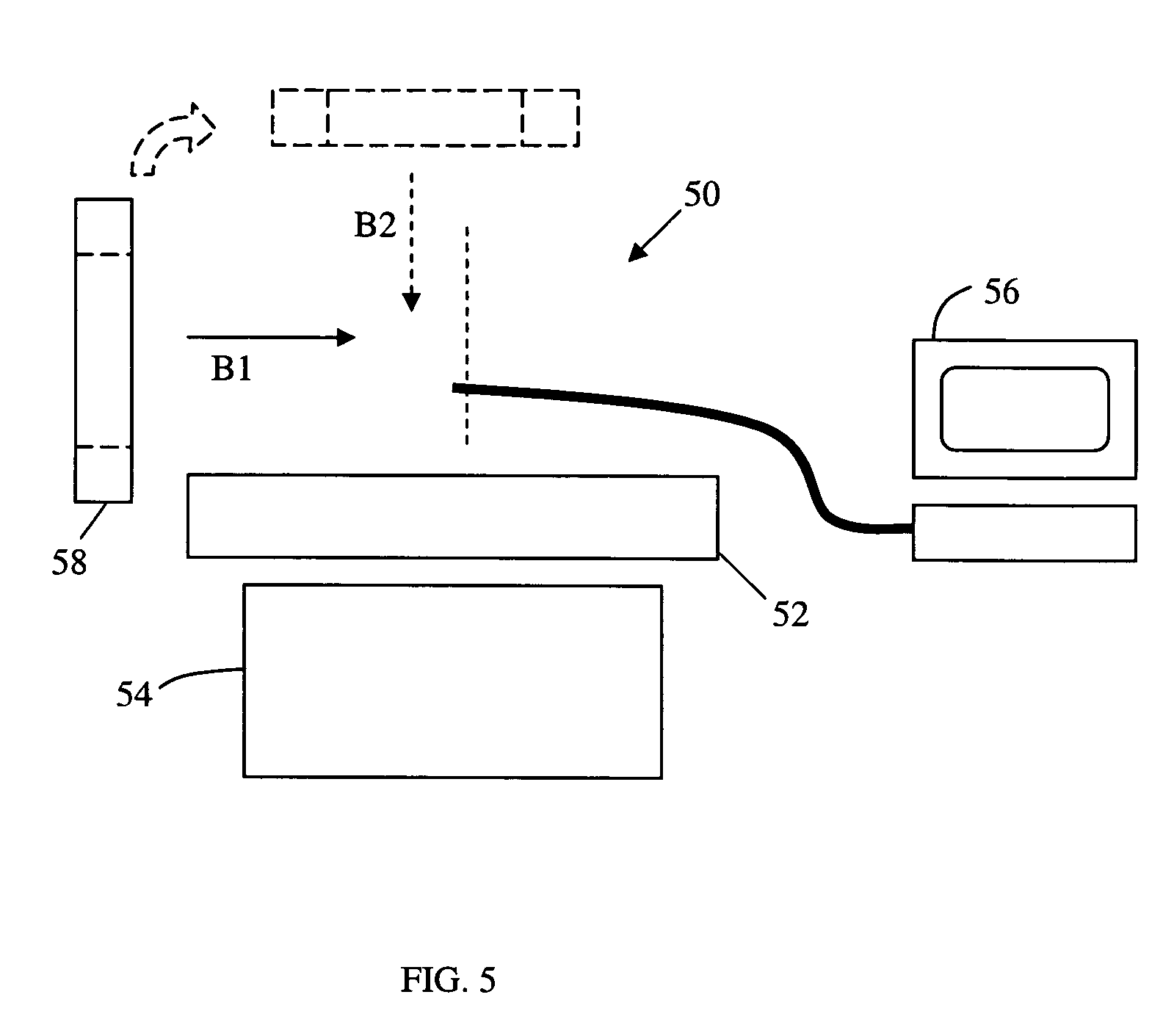
[0020] As illustrated in FIG. 5, this invention indicated generally as 50 comprises a patient support 52. The system 50 also comprises an MR imaging apparatus 54 for imaging the operating region with static field applied to the operating region. The system 20 also comprises magnetic navigation system 56 for selectively controlling the magnetic moment generated at the distal end of the medical device to orient the distal end of the medical device with respect to the static field. The system 50 further comprises at least a first movable magnet 58, movable between at least a first position and a second position. When the magnet 58 is in its first position, it creates a first static field B1 sufficient for MR imaging of the operating region, and for navigating in the operating region. When it is desired to magnetically navigate in a direction with a component in a plane perpendicular to the first static field, the magnet(s) 58 are moved to its second position to create a second static f...

third embodiment

[0022] A combined MR imaging and magnetic navigation system in accordance with this invention indicated generally as 100, is shown in FIGS. 6, 7, and 8. The system 100 comprises a support 102 for supporting a subject during imaging and navigation procedures. The system 100 further comprises an MR imaging system 104 for imaging an operating region with a static magnetic field applied to the operating region. The system further comprises a magnetic navigation system 106 for selectively controlling the magnetic moment generated at the distal end of the medical device to orient the distal end of the medical device with respect to a static magnetic field applied to the operating region. (This is typically achieved by controlling electric currents in one or more coils in the distal end of the medical device, or otherwise activating and deactivating magnetic elements in the distal end of the medical device.)

[0023] The system 100 also includes at least one magnet 106 for applying a static m...

first embodiment

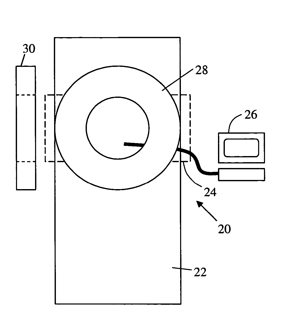
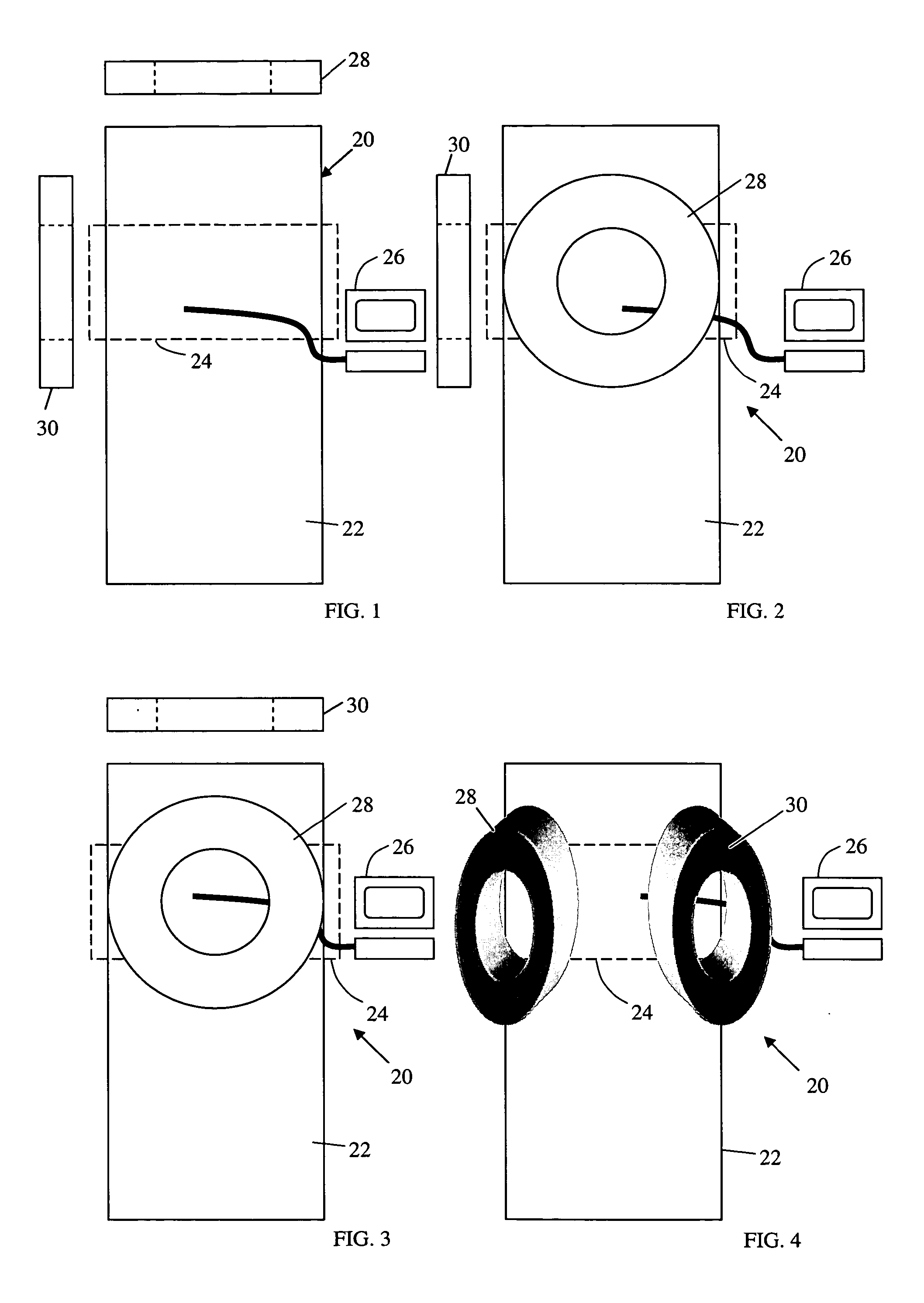
[0026] In the first embodiment the first magnet 24 is operating to apply a first static magnetic field to the operating region in a subject on the support 22. This first static field is used for MR imaging and for magnetic navigation. An elongate medical device is oriented with respect to the first static magnetic field by changing the magnetic moment at the tip of the device. Typically the devices is provided with one or more (magnetic) coils (or other magnetic elements) at its distal tip, and the magnetic moment at the tip is controlled by controlling the currents in the coils.

[0027] When it is desired to turn the distal end of the device in a direction with a component in the plane perpendicular to the first static magnetic field, the first magnet 24 is turned off, and the second magnet 26 is turned on to establish a second magnetic field in a second direction different from the first direction. The MR imaging can continue, using this second magnetic field, and because the direct...


PUM


Abstract

A system for magnetically imaging an operating region in a subject and magnetically navigating a medical device within the operating region includes a first magnet for applying a static magnetic field to the operating region of sufficient strength for magnetically imaging the operating region and sufficiently strong to permit a medical device to be oriented in the operating region by creating a magnetic moment at the distal end of the medical device, and a second magnet for applying a static magnetic field to the operating region of sufficient strength for magnetically imaging the operating region and sufficiently strong to permit a medical device to be oriented in the operating region by creating a magnetic moment at the distal end of the medical device. In an alternate construction, the system includes a first magnet that is movable between a first position to apply a first static magnetic field to the operating region and a second position to apply a second static magnetic field to the operating region. The method of the invention includes applying a first static magnetic field to the operating region and MR imaging and magnetically navigating a device in the first static field, and then applying a second static magnetic field to the operating region, in a different direction than the first direction, and MR imaging and magnetically navigating a device in the second static field.

Description

CROSS-REFERENCE TO A PRIOR APPLICATION [0001] This application claims priority of U.S. Patent Application Ser. No. 60 / 518,496, filed Nov. 7, 2003, the disclosure of which is incorporated by reference.BACKGROUND OF THE INVENTION [0002] This invention relates to the MR imaging of, and magnetic navigation of devices in, an operating region in a subject. [0003] MR imaging provides high quality medically useful images of regions of the body without exposure of the subject or the physician to x-rays. Magnetic navigation of devices allows fast and accurate control of very small, highly flexible devices by selectively changing an externally applied magnetic field. It has been proposed to use the static magnetic field of an MR imaging system to magnetically navigate devices in an operating region in a subject by selectively changing a magnetic moment at the distal end of the device, typically by changing the currents in coils disposed in the end of the device. Examples of such devices are di...

Claims


Application Information

Patent Timeline
IPC IPC(8): A61B19/00G01R33/28G01R33/38
CPCA61B19/22A61B2019/2253A61B2019/2261G01R33/3808G01R33/285G01R33/3806A61B2019/5236A61B34/70A61B34/73A61B2034/732A61B2090/374
Inventor RITTER, ROGERS C.VISWANATHAN, RAJU R.HASTINGS, ROGER N.
Owner STEREOTAXIS
Why Eureka
Try Eureka