
UHF near-field RFID reader antenna with reconfigurable identification area

A technology for identifying areas and readers, which is applied to antennas, resonant antennas, parts of resonant antennas, etc., can solve problems such as small identification areas, reduced identification areas, and limited loop antenna perimeter size, and achieves a simple and compact structure , The effect of easy processing and production

Active Publication Date: 2020-11-06
HUAIAN COLLEGE OF INFORMATION TECH
View PDF5 Cites 1 Cited by
  • Summary
  • Abstract
  • Description
  • Claims
  • Application Information

AI Technical Summary

Problems solved by technology

[0003] For the traditional loop reader antenna, when it works in the UHF frequency band, the current on the loop reverses, resulting in the generation of identification blind spots, which greatly reduces the identification area. Therefore, how to expand the identification area is a research in recent years. hotspot
Generally speaking, there are three methods as follows: one is to segment the electrically large-sized loop antenna, and load lumped or distributed capacitance between the segments to realize the same direction of loop surface current; the other is to use two or four even The poles are combined into a circular ring or a square ring, and the dipoles are fed with equal phases to achieve the same current direction; the above two methods can expand the area of ​​​​the identification area, but are still limited by the perimeter size of the loop antenna , it is difficult to further expand the identification area; the third is to construct reverse current pairs to enhance the near-field magnetic field between the reverse current pairs. This method has a simple structure, but the identification area is small
The identification area of ​​the reader antenna based on the above three methods is difficult to further expand, and the fixed area does not have reconfigurability

Method used


Image

  • UHF near-field RFID reader antenna with reconfigurable identification area
  • UHF near-field RFID reader antenna with reconfigurable identification area
  • UHF near-field RFID reader antenna with reconfigurable identification area

Examples


Embodiment Construction

[0017] Below in conjunction with the accompanying drawings, the implementation of a reconfigurable UHF near-field RFID reader antenna for the identification area provided by the present invention is described in detail:

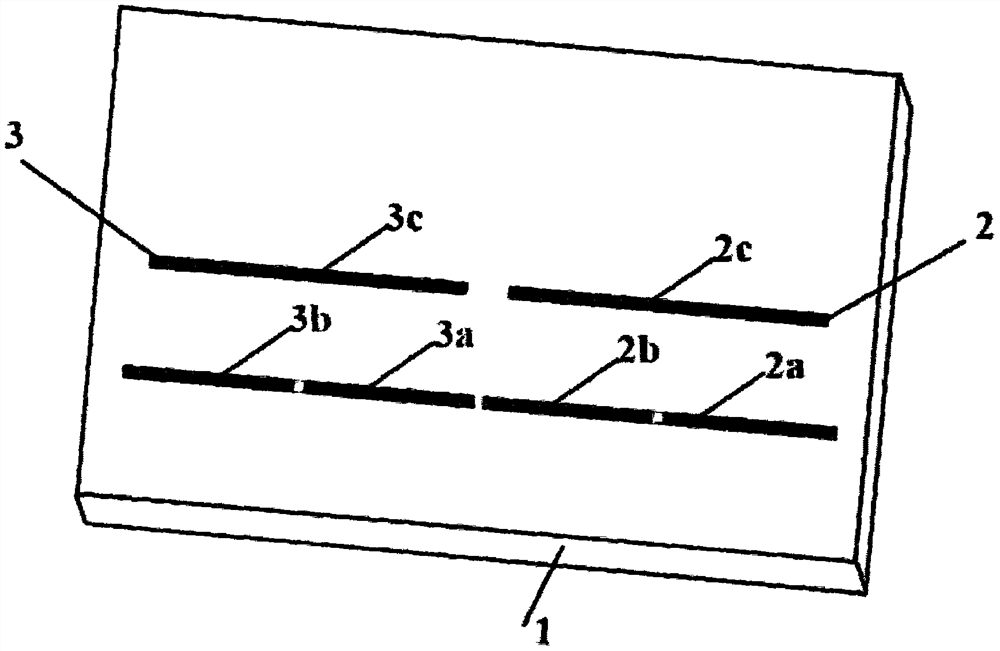
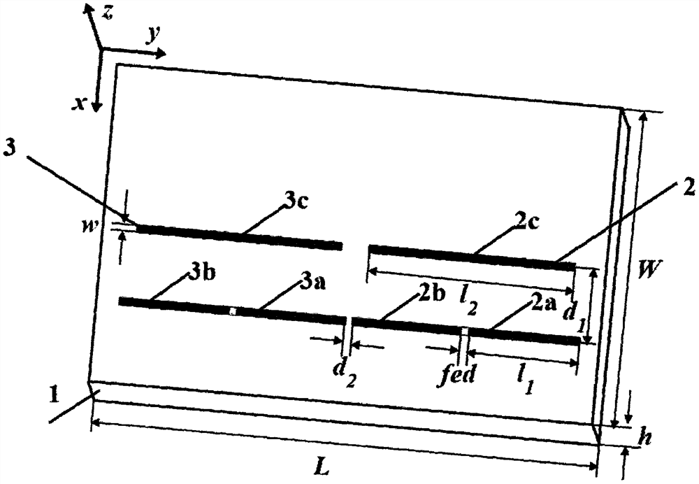
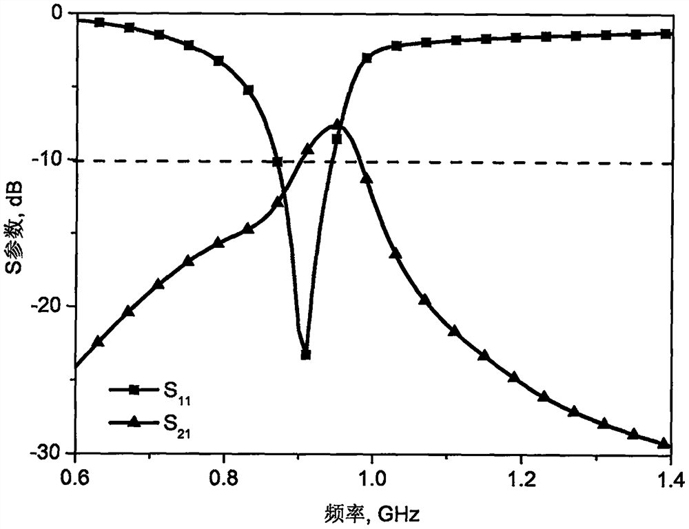
[0018] A reconfigurable UHF near-field RFID reader antenna for the identification area proposed by the present invention is as follows: figure 1 As shown, it includes a dielectric board 1 and a metal layer. The metal layer is etched on the upper surface of the dielectric board, and the power supply terminal is located on the lower surface of the dielectric board. The metal layer includes a first dipole array 2 and a second dipole array 3 . The first dipole array 2 columns include the first feeding unit and the first parasitic unit 2c; the second dipole array 3 columns include the second feeding unit and the second parasitic unit 3c. The first feed unit includes a first arm 2a and a second arm 2b; the second feed unit includes a third arm 3a and a fourth arm...


PUM


Abstract

The invention discloses a UHF near-field RFID reader antenna with a reconfigurable identification area. The UHF near-field RFID reader antenna comprises a dielectric plate and a metal layer. The metallayer is etched on the upper surface of the dielectric plate and is composed of two dipole arrays which are the same in structure and are arranged in a collinear mode. Each dipole array is composed of a feed unit and a parasitic unit, and each feed unit comprises two arms with the same length; the parasitic unit is slightly shorter than the feed unit. The distance between the parasitic unit and the feed unit is adjusted to form a reverse current pair, a strong and uniform magnetic field is generated in a large near-field area of the antenna, and the near-field label of the area is identified.Based on the superposition principle, the near-field magnetic field intensity of the middle area can be enhanced through the two dipole arrays which are arranged in the collinear mode and conduct equal-phase feeding, the near-field magnetic field is made to be uniform by adjusting the distance between the dipole arrays, and the recognition area of the antenna is expanded; by adjusting the feed phase difference of the two dipole arrays, the reconfiguration of the identification area is realized.

Description

technical field [0001] The invention belongs to the field of electromagnetic field and microwave technology, in particular to a UHF near-field RFID reader antenna with reconfigurable identification area. Background technique [0002] The near-field radio frequency identification (Radio Frequency Identification, RFID) system is based on magnetic field coupling and works in the low frequency (Low Frequency, LF) or high frequency (High Frequency, HF) frequency band, which is not easily affected by the environment where the tag is located, but its recognition distance is limited by Limited and low reading rate; far-field RFID systems generally use Ultra High Frequency (UHF) or Microwave (MicroWave, MW) frequency bands, which have high reading rates and long recognition distances, but are easily affected by the environment of reader tags. Combining the advantages of near and far fields, the researchers proposed a UHF near-field RFID system, which is widely used in retail, logisti...

Claims


Application Information

Patent Timeline
Patent Type & Authority Applications(China)
IPC IPC(8): H01Q3/32H01Q9/04H01Q9/14
CPCH01Q3/32H01Q9/04H01Q9/14
Inventor 于正永韩睿史红彦王志勃董进徐义晗
Owner HUAIAN COLLEGE OF INFORMATION TECH
Learn More