Kickout flashing and associated assembly and method

a technology of adhesive assembly and flashing, which is applied in the direction of snow traps, roof drainage, transportation and packaging, etc., can solve the problems of requiring time for seal formation, damage to the wall or the roof, and eventually leakag

Active Publication Date: 2005-08-25
ALLEN L ROSS
View PDF16 Cites 21 Cited by
  • Summary
  • Abstract
  • Description
  • Claims
  • Application Information

AI Technical Summary

Benefits of technology

[0005] The present invention provides a kickout flashing and an associated assembly and method for directing water along an interface defined between a roof and a wall. The flashing can be formed with an angled configuration so that the flashing does not need to be cut and bent to form an angle during installation. For example, the flashing can be formed of a unitary molded plastic member. Further, the flashing can be reversible so that the same flashing can be selectively installed at interfaces of different configurations.

Problems solved by technology

The cut made in the flashing to facilitate bending and forming the kickout can result in leaking of water, which can flow into the wall behind the siding or under the shingles to the roof, thereby causing damage to the wall or the roof.
Conventional kickouts are sometimes sealed with a weld or solder joint or with caulk, but such seals require time for forming and can eventually leak, especially in the case of a caulk seal.

Method used


Image

  • Kickout flashing and associated assembly and method
  • Kickout flashing and associated assembly and method

Examples


Embodiment Construction

[0014] The present invention now will be described more fully hereinafter with reference to the accompanying drawings, in which preferred embodiments of the invention are shown. This invention may, however, be embodied in many different forms and should not be construed as limited to the embodiments set forth herein; rather, these embodiments are provided so that this disclosure will be thorough and complete, and will fully convey the scope of the invention to those skilled in the art. Like numbers refer to like elements throughout.

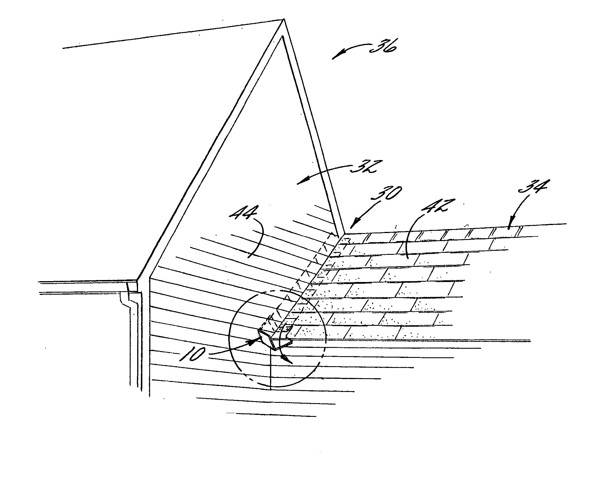
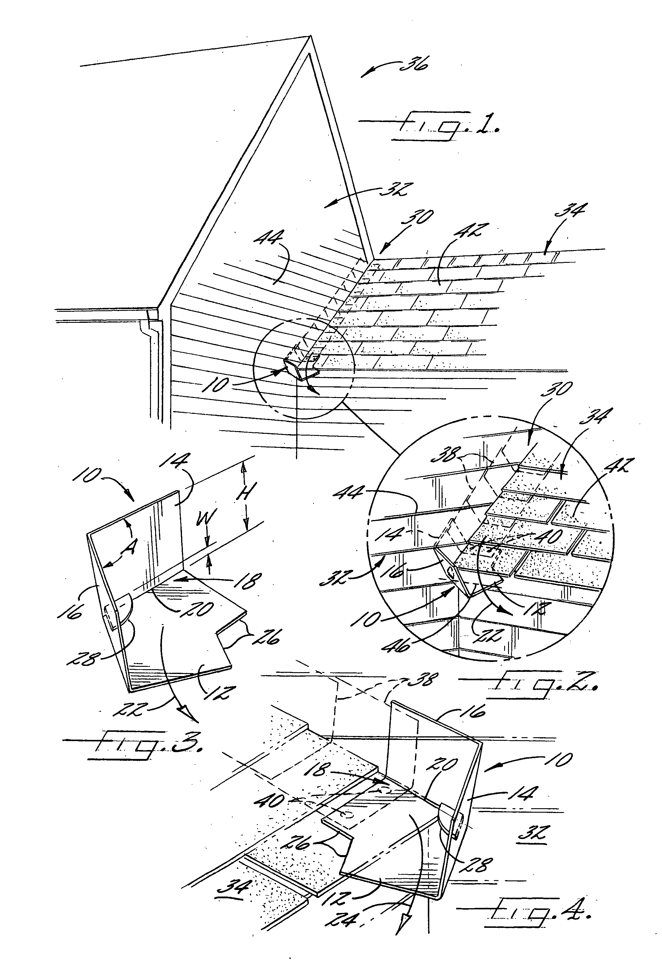
[0015] Referring to the drawings and, in particular, to FIG. 1, there is shown a kickout flashing 10 according to one embodiment of the present invention installed at the interface 30 of a building 36 where a slanted roof 34 abuts a vertical wall 32. The kickout flashing 10 can be used in conjunction with conventional pieces of flashing, such as L-shaped flashings 38 that are arranged in a successively overlapping configuration along the wall-roof interf...


PUM


Abstract

A flashing and associated assembly and method for directing water along an interface between a roof and a wall are provided. The flashing, which can be formed as a unitary molded plastic member, has an angled configuration. In particular, a roof portion of the flashing is configured to be disposed on the roof, and first and second flanges extend perpendicularly from the roof portion to define a continuous passage for receiving water. The flanges define an obtuse angle therebetween so that when one flange is disposed against the wall the other flange is configured to direct water flowing along the passage away from the wall. The flashing can be reversible so that the same flashing can be selectively installed at wall-roof interfaces of different configurations.

Description

FIELD OF THE INVENTION [0001] This invention relates to a kickout flashing for directing water along an interface between members of a building, such as a vertical wall and a roof abutting the wall. BACKGROUND OF THE INVENTION [0002] Flashings are typically disposed at the interfaces formed between roofs and walls of buildings to prevent water from leaking through the interfaces to the underlying structures. One such interface in a typical building construction is the intersection of a slanted roof with a vertical exterior wall that extends higher than the roof such that the intersection extends perpendicular to the wall at a slant defined by the angle of the roof. L-shaped pieces of flexible metal flashing are typically provided at the intersection so that a first leg of each flashing is disposed against the roof and a perpendicular second leg is disposed against the wall. Successive pieces of the flashing are installed along the intersection so that each piece of flashing is overl...

Claims


Application Information

Patent Timeline
Patent Type & Authority Applications(United States)
IPC IPC(8): E04D13/04E04D13/147
CPCE04D13/1478E04D2013/0486E04D2013/045
Inventor ALLEN, L. ROSS
Owner ALLEN L ROSS
Why Eureka
Try Eureka