Computer-controlled dental treatment system and method

Inactive Publication Date: 2005-08-25
COHEN YECHIEL
View PDF10 Cites 62 Cited by
  • Summary
  • Abstract
  • Description
  • Claims
  • Application Information

AI Technical Summary

Benefits of technology

[0004] An object of the present invention is to provide a dental ...

Problems solved by technology

All such systems, however, still require the actual treatments to be rendered by the dentist, and therefore, they not only requires the dentist to ...

Method used


Image

  • Computer-controlled dental treatment system and method
  • Computer-controlled dental treatment system and method
  • Computer-controlled dental treatment system and method

Examples


Embodiment Construction

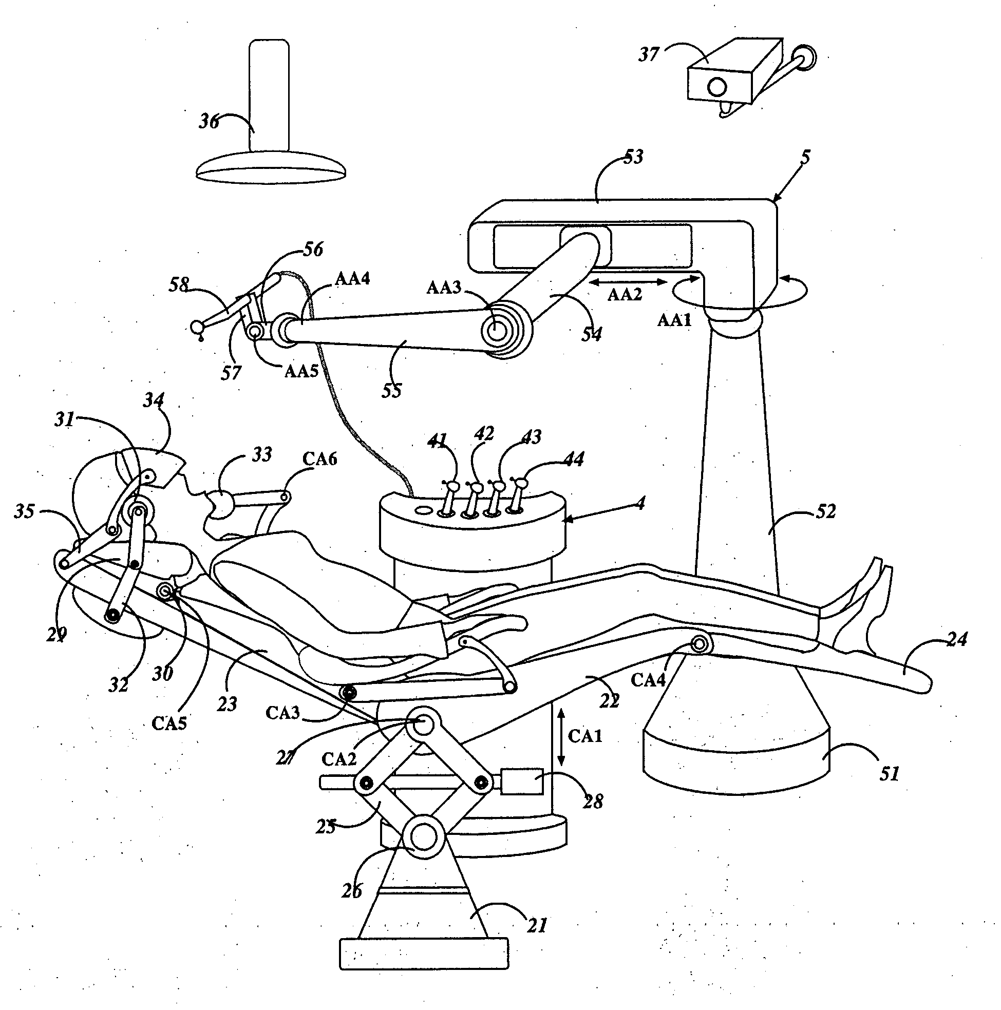
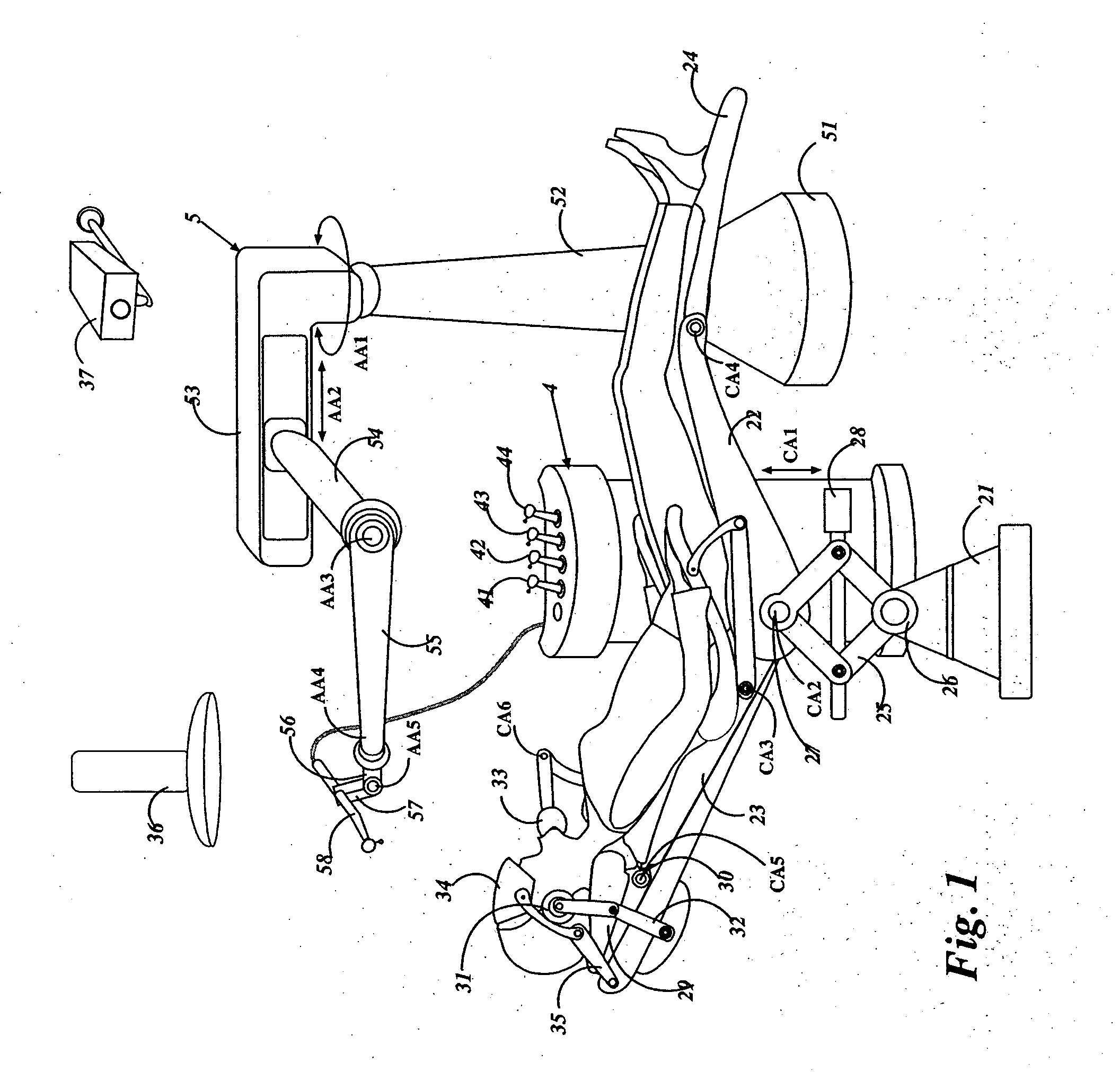
[0019] With reference to FIG. 1, there is illustrated a dental chair, generally designated 2, which may be fully or partially controlled automatically according to the specific characteristics of the patient and the specific dental treatment to be rendered. Also illustrated in FIG. 1 are a dental tray 4 for holding the various dental tools, and a robotic arm 5, which is also automatically controlled in accordance with the specific treatment to be rendered to the patient and the specific characteristics of the patient.

[0020] Thus, the dental chair 2 illustrated in FIG. 1 includes a base 21 mounting a seat 22, back rest 23 and leg rest 24 for supporting the patient in a number of different positions as may be required according to the specific characteristics of the patient and the treatment to be rendered. The seat 22, back rest 23 and leg rest 24 are mounted for vertical adjustment by a lazy tongs mechanism 25 which is pivotably mounted to the base 21 about a horizontal axis 26. Th...


PUM


Abstract

A computer-controlled dental treatment system, includes: a dental chair for receiving a patient to be treated; a robotic arm carrying a dental tool holder for holding a dental tool to be used in rendering a selected dental treatment, and for manipulating the dental tool with respect to the patient's head during the dental treatment; and a control system programmable to control the robotic arm to manipulate the dental tool in accordance with the selected dental treatment to be rendered to the patient.

Description

RELATED APPLICATION [0001] The present application is related to Provisional Application Ser. No. 60 / 540,355, filed Feb. 2, 2004, and claims the priority date of that application.FIELD AND BACKGROUND OF THE INVENTION [0002] The present invention relates to a dental treatment system and method, and particularly to a computer-controlled dental treatment system and method. [0003] A number of computer-based systems and methods have been proposed for aiding a dentist in performing a particular dental treatment. For example, U.S. Pat. No. 6,640,128 relates to a method and device for assisting the dentist in navigating a dental tool during a dental treatment; U.S. Pat. No. 6,602,070 discloses a technique for generating and displaying a plurality of treatment paths for selection by the dentist; U.S. Pat. No. 5,453,009 discloses a technique for examining and storing patient mouth data regarding possible dental diseases or problems and for generating a sequence of treatments to guide the dent...

Claims


Application Information

Patent Timeline
IPC IPC(8): A61C1/02A61C1/08A61G15/14B25J9/04B25J9/16
CPCA61C1/082B25J9/041A61G15/14
Inventor COHEN, YECHIEL
Owner COHEN YECHIEL
Why Eureka
Try Eureka