Methods of manufacture and use of endoluminal devices

a technology of endoluminal devices and manufacturing methods, applied in the field of seamless endoluminal devices, can solve the problems of cell ischemia and/or death, increase the mortality of patients with significant coronary disease (18%), and surgery, etc., to achieve sufficient radiopaque and increase the capture efficiency

Inactive Publication Date: 2005-09-01
WL GORE & ASSOC INC
View PDF96 Cites 134 Cited by
  • Summary
  • Abstract
  • Description
  • Claims
  • Application Information

AI Technical Summary

Benefits of technology

[0024] A still further object of the present invention is to provide a seamless, low-profile filter that minimally perturbs flow.
[0025] A further aspect of the present invention to provide a low profile, seamless filter that is readily connected to the guidewire of a endoluminal deployment system.
[0027] A further aspect of the invention is to provide a filter frame, which can be rendered sufficiently radiopaque.
[0028] A further aspect of the present invention is to provide filters which have increased capture efficiency and are capable of providing drug delivery.

Problems solved by technology

In therapeutic vascular procedures, liberation of embolic debris (e.g., thrombus, clot, atheromatous plaque, etc.) can obstruct perfusion of the downstream vasculature, resulting in cellular ischemia and / or death.
Additionally, percutaneous transluminal coronary angioplasty (PTCA) with or without adjunctive stent placement, surgical coronary artery by-pass grafting, percutaneous renal artery revascularization, and endovascular aortic aneurysm repair have also been associated with complications attributable to atheromatous embolization.
Surgery, however, does have several limitations, including: increased mortality in patients with significant coronary disease (18%), restriction to the cervical portion of the extra-cranial vasculature, a predeliction for cranial palsies (7.6%-27%), and restenosis (5%-19%; Yadav, Elective stenting of the extracranial carotid arteries.
Despite the potential benefits of this approach, emboli liberated during trans-catheter carotid intervention can place the patient at risk of stroke.
Additionally, prolapse of atheromatous material through the interstices of the stent can embolize after the completion of the procedure.
This concern is warranted due to the significant morbidity and / or mortality that such an event might produce.
The principle drawback of occlusion balloon techniques stem from the fact that during actuation distal blood flow is completely inhibited, which can result in ischemic pain, distal stasis / thrombosis, and difficulties with fluoroscopic visualization due to contrast wash-out through the treated vascular segment.
The device also presents a large profile during positioning and is difficult to construct.
During positioning within a vessel, the filter material is not fully constrained so that, as the device is positioned through and past a clot, the filter material can potentially snag clot material creating freely floating emboli, prior to deployment.
This device may also be difficult to manufacture.
The filter, however, may not seal around the interior vessel wall.
This umbrella-type device is shallow when deployed so that, as it is being closed for removal, particles have the potential to escape.
Other disadvantages associated with the predicate devices are that the steerability of the guidewire may be altered as compared to the conventional guidewires due to the presence and size of the filter.
The guidewire, for example, may bend, kink, and / or loop around in the vessel, making insertion of the filter through a complex vascular lesion difficult.
Also, delivery of such devices in a low-profile pre-deployment configuration can be difficult.
Further, some devices include complex and cumbersome actuation mechanisms.
Also, retrieving such capture devices after they have captured emboli may be difficult.
Current filter designs suffer from numerous disadvantages due to their construction.
A typical wire frame constructed in this manner is subject to a limited range of manipulation after the wires are adhered, since the welds or attachment areas are at an increased risk of failure due to the physical constraints of the welds themselves.
Additionally, the welding of metal involves the application of increased heat to join a wire pair and a risk exists of the mesh, formed by the pairs, dripping or otherwise malforming due to the proclivity of metal to run before cooling.
A further disadvantage to a typical wire filter is that the filter element is difficult to apply to the frame since the filter is normally applied as a sock, tube, or other such shape.
An additional problem evident in this construction is that the filter element could be abraded by a protrusion formed by a weld in a wire pair.
Such an abrasion could form a weakness or a tear in the filter and undermine its desired functionality.
Existing guidewire-based embolic filtering devices are inadequate for these and other purposes.

Method used


Image

  • Methods of manufacture and use of endoluminal devices
  • Methods of manufacture and use of endoluminal devices
  • Methods of manufacture and use of endoluminal devices

Examples


example 1

Nitinol Sheet Filter Frame and Integral Tethers

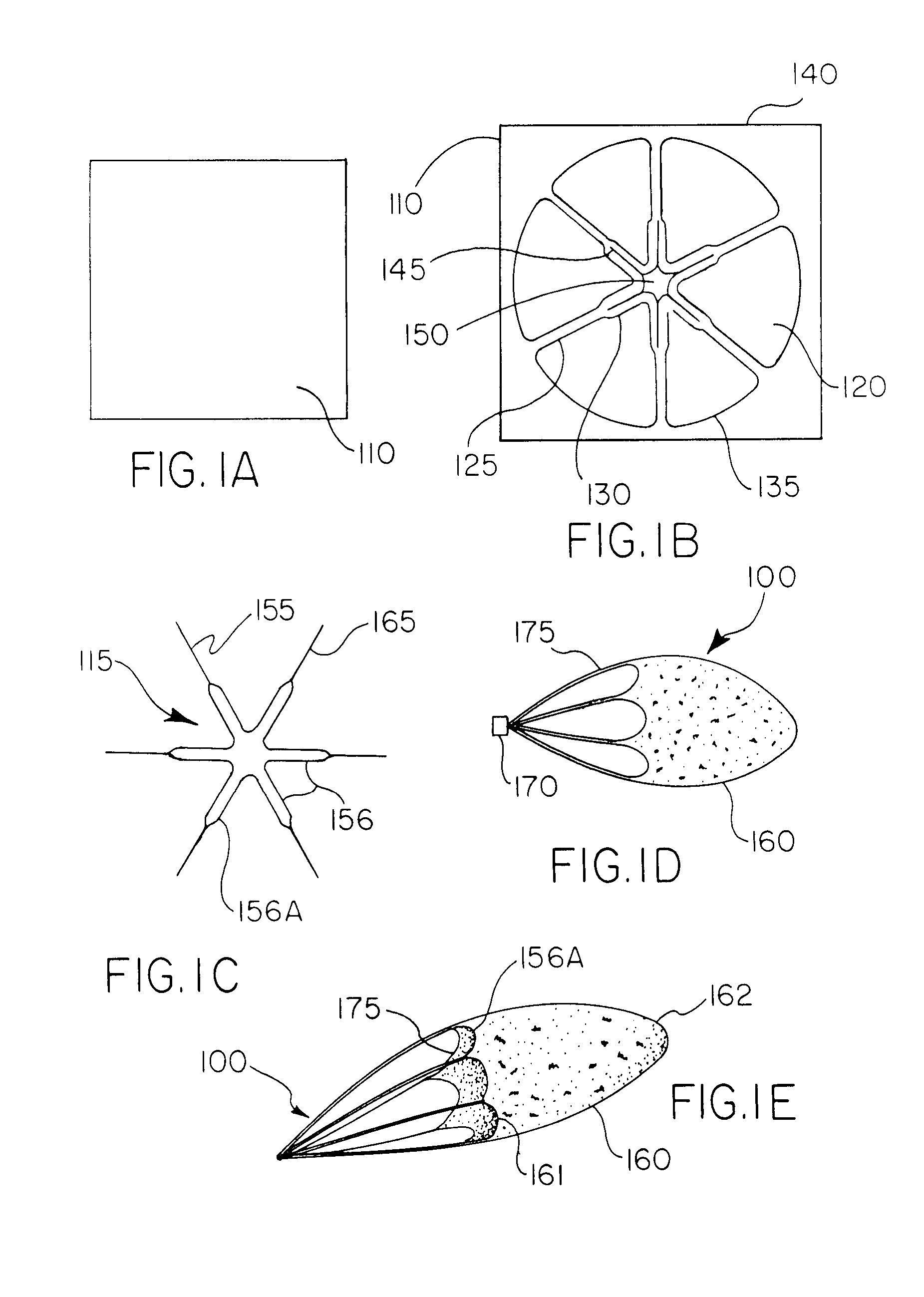
[0127] A radially-symmetric geometrical pattern comprising interconnected struts forming closed polygonal shaped cells was chemically etched from a sheet of Nitinol (NiTi) to produce a skeletal filter frame. The etching, preferably photoetching of Nitinol (Kemac Technologies, Irwindale, Calif.) is continued to achieve a desirable material thickness, to optimize the moment of inertia of the struts and to polish the surface finish.

[0128] This filter frame is then subjected to a thermal treatment to set the phase transition temperature of the NiTi to approximately 37° C. by heating the filter frame to a temperature of about 450° C. for about 10 minutes in an air convection oven (Carbolite Corporation, Sheffield, England) followed by a rapid quench in ambient temperature water.

[0129] The NiTi filter frame was then laminated between two (2) layers of an adhesive-coated porous polymer. The layers were positioned with the adhesive sides fac...

example 2

Nitinol Tube Filter Frame and Integral Tethers

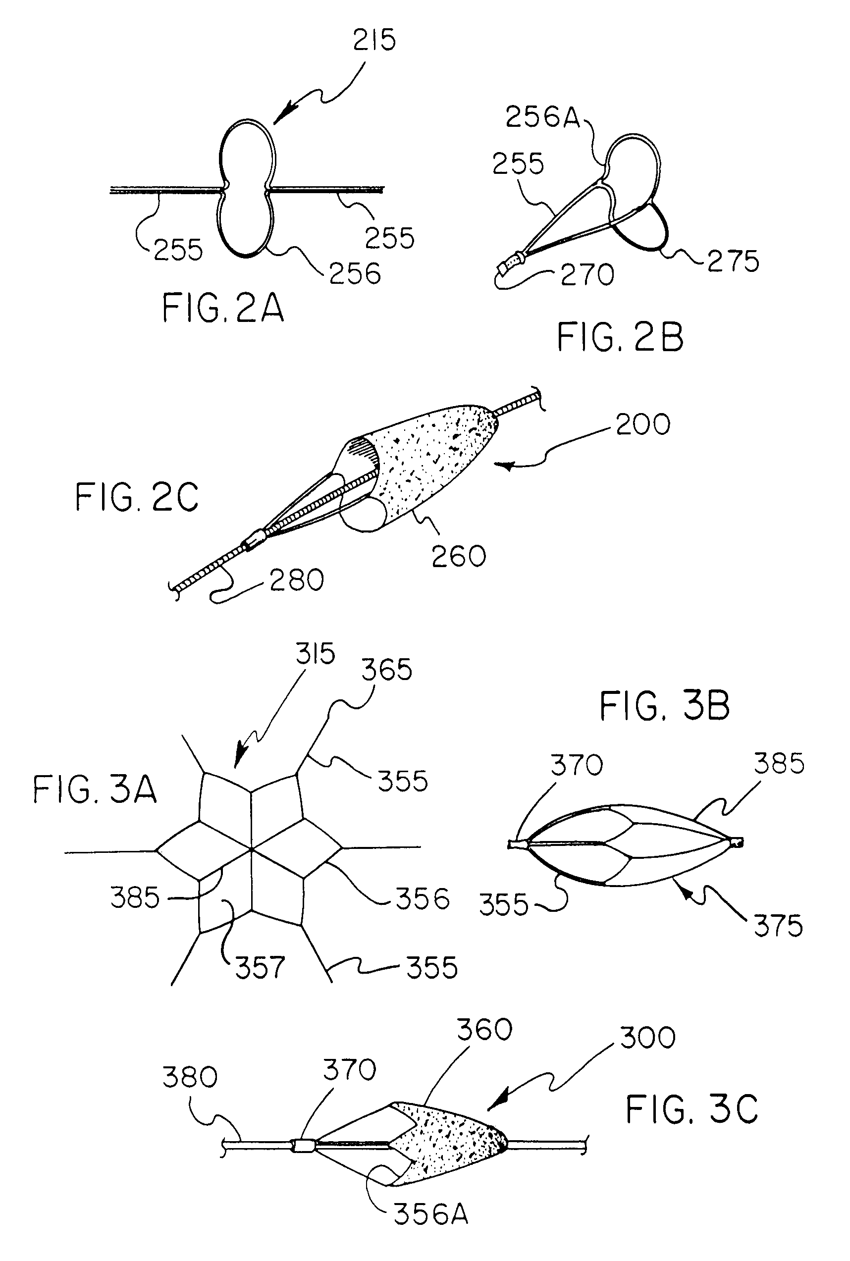
[0133] A 1.3 mm Nitinol tube with a wall thickness of approx 0.1 mm (obtained from Nitinol Devices and Components, Fremenot, Calif.) was laser cut (Laserage Technologies Inc, Waukegan, Ill.) to a single, undulating 6 apex ring geometry with integral tethers. This frame was then lightly grit blasted at 40 psi with 20 micron silicon carbide media in a grit blasting machine made by Comco Inc, Burbank, Calif. The ring with integral tethers was then gently pushed up a tapered mandrel until it achieved a functional size of approx. 6 mm. The ring, tethers and mandrel were then subjected to a thermal treatment to set the phase transition temperature of the NiTi to approximately 37° C. in an air convection oven (Carbolite Corporation, Sheffield, England) One skilled in the art will realize that variances in the geometry, metallurgy, thickness and heat treating of the filter frame can all be varied to create alternate embodiments with varying des...


PUM


Abstract

A seamless, self-expanding implantable device having a low profile is disclosed along with methods of making and using the same. The implantable device includes a frame cut out of a single piece of material that is formed into a three-dimensional shape. The implantable device may comprise an embolic filter, stent, or other implantable structure. The present invention also allows complicated frame structures to be easily formed from planar sheets of starting material, such as through laser cutting, stamping, photo-etching, or other cutting techniques.

Description

CROSS-REFERENCE TO RELATED APPLICATIONS [0001] This application is a Division of U.S. patent application Ser. No. 10 / 113,724 filed Apr. 1, 2002.FIELD OF THE INVENTION [0002] The present invention relates to seamless endoluminal devices including frame patterns for filters, their manufacture and use in the filtration and / or removal of embolic matter from fluids flowing in tubular body lumens including, but not limited to: blood flow in arteries and veins; airflow within the respiratory tract; and the flow of urine in the urinary tract. The seamless filter of the present invention may be self-expanding, is deployable via a guidewire-based system and has a low profile. BACKGROUND OF THE INVENTION [0003] Embolic protection is a concept of growing clinical importance directed at reducing the risk of embolic complications associated with interventional (i.e., transcatheter) and surgical procedures. In therapeutic vascular procedures, liberation of embolic debris (e.g., thrombus, clot, ath...

Claims


Application Information

Patent Timeline
Patent Type & Authority Applications(United States)
IPC IPC(8): A61B17/00A61F2/01A61F2/84
CPCA61F2/013A61F2230/0093A61F2002/016A61F2002/018A61F2/01A61B17/12109A61F2230/0006A61F2230/0015A61F2230/005A61F2230/0067A61F2230/0069A61F2230/0076A61F2230/008A61F2230/0091A61F2/91A61F2/0105A61F2/0108
Inventor CULLY, EDWARD H.VONESH, MICHAEL J.
Owner WL GORE & ASSOC INC
Why Eureka
Try Eureka