
Artificial disc device

a technology of artificial discs and discs, which is applied in the field of multi-piece implants, can solve the problems of sciatica or pain, urinary and fecal incontinence, and nerve system interference,

Inactive Publication Date: 2005-09-01
PIONEER SURGICAL TECH INC
View PDF101 Cites 276 Cited by
  • Summary
  • Abstract
  • Description
  • Claims
  • Application Information

AI Technical Summary

Benefits of technology

[0020] In accordance with one aspect of the present invention, a multi-piece nucleus implant device is disclosed for replacing a nucleus removed by a nucleotomy. The implant may include at least a first shell or plate member, a second shell or plate member, and a bearing member providing at least one direction of movement between the two shells, and preferably being a polyaxial articulating bearing member. The articulating bearing member provides for the natural movement of the spine including flexion / extension, lateral bending, and rotation. Each of the plate members and the articulating bearing member are generally formed to be rigid. Therefore, the implant is capable of supporting the compressive and cyclic loads required of a natural disc.

Problems solved by technology

Although many factors may be responsible for causing lower back pain, a principal factor is damage or degeneration of an intervertebral spinal disc resulting in impingement on the nerve system, specifically the spinal cord, located within the spine.
Such impingement may result in, for instance, loss of mobility, urinary and fecal incontinence, and sciatica or pain experienced in the extremities.
Damage to or degeneration of a spinal disc can result from a number of factors such as abuse or age.
Most frequently, disc degeneration results from damage occurring to the annulus such that the flowable nucleus material may leak or seep out of the annulus.
Disc degeneration also can occur in other ways, such as by being deprived of nutrient flow leading to a dried and susceptible to damage disc.
However, the current practice of each of these procedures typically has certain limitations.
With fusion, making a portion of the spine generally rigid produces a reduction in mobility, and drastically alters normal load distribution along the spinal column.
The increased stress and strain on the non-fused portions may lead to accelerated disc degeneration of the non-fused portions, particularly the adjacent levels of the spine.
However, current discectomy often may lead to a reduction of the disc space between adjacent vertebrae, as well as instability in the affected portion of the spine.
Such long-term effects with current discectomy often result in further surgery several years after the initial discectomy surgery.
However, little success has been experienced with prosthetic disc implants due to the complexity of the natural disc structure and biomechanical properties of a natural spinal disc.
In using disc implants, there are a number of issues with currently known TDPs and DNPs that attempt to mimic the biomechanical properties of a natural intervertebral disc.
However, these discs have typically been found incapable of maintaining structural integrity over the cyclic load life required of a disc that may be employed for 20 or more years.
Undesirably, loading between the ball and the end plates was highly concentrated such that bone subsidence caused the vertebrae to collapse around the ball.
Another issue is implant extrusion, defined as the tendencies for an implant not to remain seated, and for the implant to back out of its intended seat.
This, alone, violates the integrity of the end plates to a degree where revision surgery is limited, possibly to spinal fusion for immobilizing the spinal segment and fusing the vertebrae with posterior pedicle instrumentation.
Violation of the vertebrae by the securement may cause bleeding, or calcification of the end plate, either of which can result in pain, loss of mobility, necrosis, or deterioration of any implant device.
In mating the implant with the end plates, stress concentrations may result due to contour mismatch, such as occur with the above-described implant ball.
This requires greater invasiveness, which complicates surgery and leads to greater time for recovery and post-surgical pain.
Furthermore, this often destroys any remaining utility for the annulus as a large incision must be made, in the event it is even retained.
As the annulus does not heal well and suturing the annulus is difficult due to its tissue properties, the ability of the annulus to retain the implant is diminished if not eliminated, and implant extrusion often is not prevented by the annulus.
However, these implants typically rely on a structure that is entirely resiliently deformable.
Therefore, these implants typically are limited to providing shock absorption, while not providing range of motion with high-cyclic loading or sufficient support.
Because of the geometry and structure of a vertebra, a natural disc, and an artificial disc implant, posterior surgical procedures do not typically permit the access required for evacuation of the disc space and implantation of the prosthetic device.
More particularly, it is believed that failure to provide the normal range of motion has the deleterious effects, as discussed above, of spinal fusion.
Some procedures and devices rely on lateral or anterior surgical procedures, which are highly invasive and traumatic and which carry high surgical risk.

Method used


Image

  • Artificial disc device
  • Artificial disc device
  • Artificial disc device

Examples


Embodiment Construction

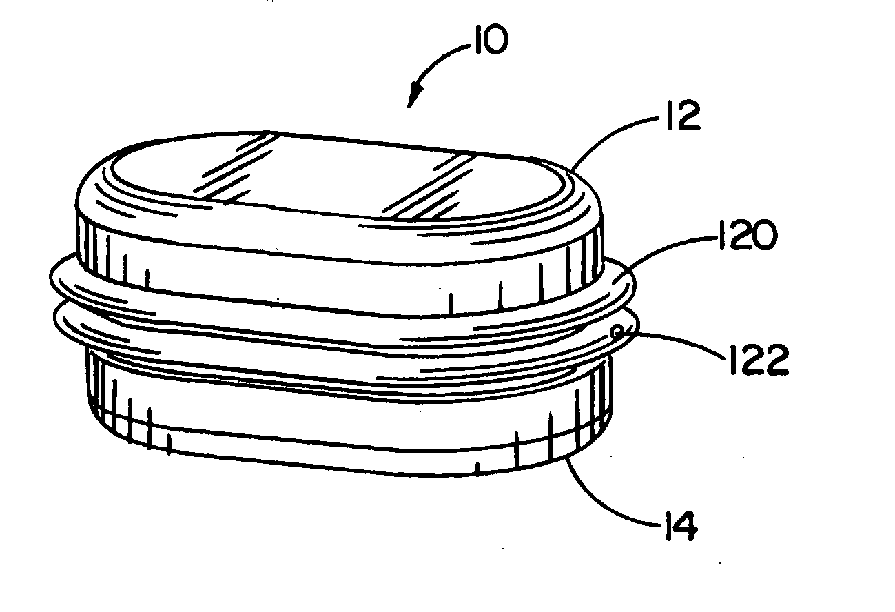
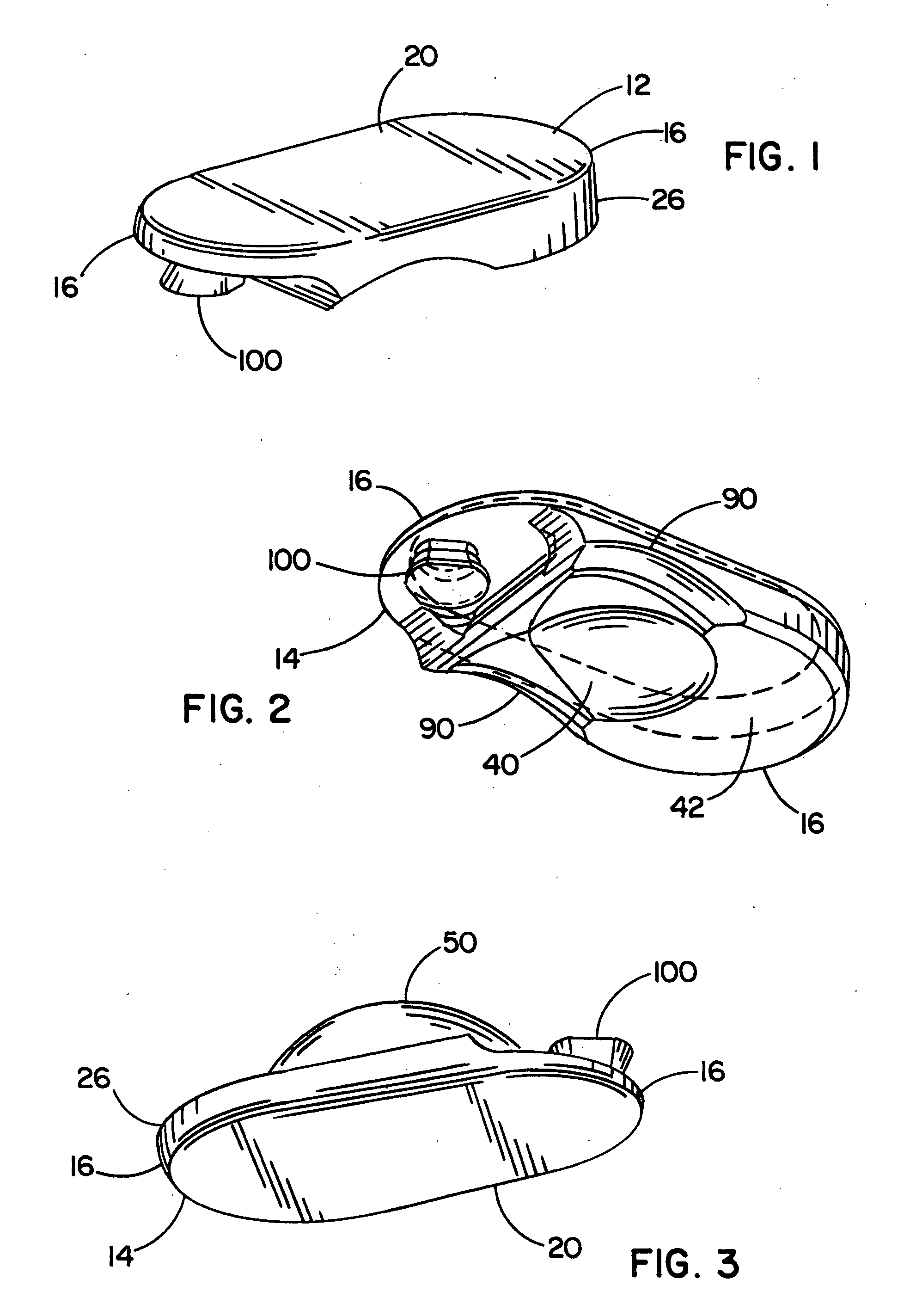
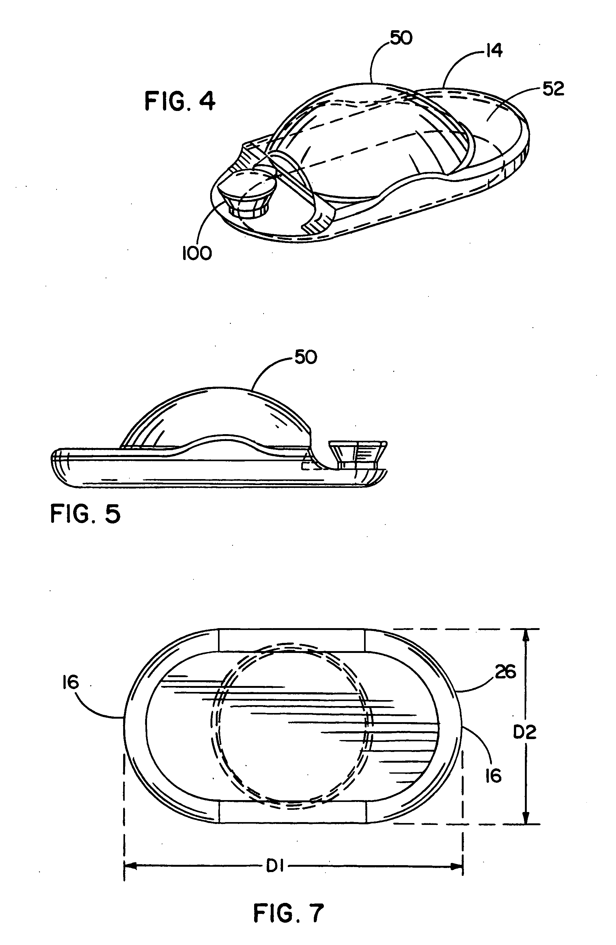
[0117] Referring now to the FIGURES, one embodiment of an implant device 10 is depicted including a top shell 12 and a bottom shell 14. As used herein, the terms top shell and bottom shell are simply referential for the arrangement of the shells as depicted, and the arrangement could be reversed. The implant 10 is a prosthetic nucleus implant for replacing the nucleus of a damaged natural spinal disc. The nucleus of the natural spinal disc is generally cleared by a procedure known as a nucleotomy where an incision is made in an annulus surrounding the nucleus, whereupon the nucleus is substantially removed. Typically, a small amount of the viscous nuclear material remains in the disc space, and this material can be used to provide an interface for reducing possible stress points due to incongruities between the implant 10 and end plates of the adjacent vertebrae.

[0118] One embodiment of the implant 10 is inserted through the incision in the annulus such that the annulus remains att...


PUM

PropertyMeasurementUnit
15° angleaaaaaaaaaa
angle of deflectionaaaaaaaaaa
angleaaaaaaaaaa

Abstract

An artificial disc device for replacing a damaged nucleus is disclosed. In one form, the device may be inserted in components such that the device may be assembled within and retained by the natural annulus therein. In another form, the device may be inserted into the natural annulus in a collapsed or compressed state or arrangement and then be expanded within and retained by the annulus therein. In a further form, the device may be provided with a releasable connection so that the device may be connected in an insertion configuration and may be released in an operable configuration. Insertion tools and methods are also disclosed.

Description

CROSS-REFERENCE To RELATED APPLICATION [0001] This application is a continuation-in-part of U.S. patent application Ser. No. 10 / 282,620, filed Oct. 29, 2002, entitled “Artificial Intervertebral Disc Device,” and is a continuation-in-part of U.S. patent application Ser. No. 10 / 692,468, filed Oct. 22, 2003, entitled “Artificial Disc Device,” the specifications of which are incorporated herein in their entirety.FIELD OF THE INVENTION [0002] The invention relates to artificial intervertebral implants and, in particular, to a multiple piece implant that permits relative articulation and / or translation of the multiple pieces. BACKGROUND OF THE INVENTION [0003] The most common orthopedic condition for which professional medical treatment is sought is lower back pain. Although many factors may be responsible for causing lower back pain, a principal factor is damage or degeneration of an intervertebral spinal disc resulting in impingement on the nerve system, specifically the spinal cord, lo...

Claims


Application Information

Patent Timeline
Patent Type & Authority Applications(United States)
IPC IPC(8): A61B17/88A61FA61F2/00A61F2/02A61F2/30A61F2/44A61F2/46
CPCA61F2/30742A61F2/30965A61F2/442A61F2/4425A61F2/4611A61F2/4684A61F2002/30014A61F2002/30016A61F2002/3008A61F2002/30113A61F2002/30123A61F2002/30125A61F2002/30133A61F2002/30158A61F2002/302A61F2002/3023A61F2002/30242A61F2002/30245A61F2002/30299A61F2002/30311A61F2002/30327A61F2002/30331A61F2002/30369A61F2002/30387A61F2002/3039A61F2002/30428A61F2002/30448A61F2002/30462A61F2002/30471A61F2002/30476A61F2002/30485A61F2002/305A61F2002/30507A61F2002/3052A61F2002/30528A61F2002/30538A61F2002/3054A61F2002/3055A61F2002/30556A61F2002/30563A61F2002/30565A61F2002/30574A61F2002/30581A61F2002/30583A61F2002/30586A61F2002/30588A61F2002/30604A61F2002/30616A61F2002/30649A61F2002/30662A61F2002/30673A61F2002/30685A61F2002/30738A61F2002/30784A61F2002/30841A61F2002/30919A61F2002/30934A61F2002/30935A61F2002/443A61F2002/444A61F2002/4627A61F2002/4681A61F2002/484A61F2210/0085A61F2220/0025A61F2220/0033A61F2220/005A61F2220/0075A61F2220/0091A61F2230/0006A61F2230/0008A61F2230/0015A61F2230/0026A61F2230/0065A61F2230/0069A61F2230/0071A61F2230/0093A61F2250/0006A61F2250/0009A61F2250/0018A61F2250/0019A61F2250/0039A61F2250/0098A61F2310/00017A61F2310/00023A61F2310/00029A61F2310/00179A61F2310/00203A61F2310/00239A61F2310/00574A61F2/484A61F2002/4628
Inventor BAO, QI-BINTRUDEAU, JEFFREY L.JANOWSKI, BRIAN PATRICKSONGER, MATTHEW N.YUAN, HANSEN A.KILPELA, THOMAS S.BERREVOETS, GREGORY
Owner PIONEER SURGICAL TECH INC
Learn More