
Goggle attachment system

a technology of goggles and attachment systems, which is applied in the direction of goggles, eye surgery, protective garments, etc., can solve the problems of two components being subject to wind interference, the goggles and helmets are not designed for easy concurrent use on the head of the wearer, etc., and achieve the effect of minimizing or eliminating fogging of the lens and maximizing air flow

Inactive Publication Date: 2005-09-08
K 2 CORP
View PDF34 Cites 27 Cited by
  • Summary
  • Abstract
  • Description
  • Claims
  • Application Information

AI Technical Summary

Benefits of technology

[0011] The device herein disclosed features a system of rotationally engageable outriggers for goggles which may be worn on the head of the user either with or without a helmet or other headgear. The outriggers are dimensioned to have aerodynamic exterior surfaces that work to maximize air flow through the eye cavity behind the goggle lens and minimize or eliminate fogging of the lens by forming negative air pressure areas adjacent to apertures communicating through the outrigger.
[0012] The outriggers would come in a plurality of different configurations to allow for a plurality of different mountings to either the head or a helmet on the head of a user. When the outriggers are adapted for cooperative engagement with a helmet, the helmet goggle combination yields an especially aerodynamic combined helmet and goggle surface, yet still maximizes airflow through the eye cavity behind the lens.
[0013] The easy mounting system is accomplished by having the outriggers engaged with a strap, cord, pin, or other means for attachment to the head of a user at a trailing end, and a biased or other hinged engagement to the goggle at the engagement end of the outrigger.

Problems solved by technology

Commonly however, the goggles are designed to be worn over the eyes, and the helmet is designed for wearing over the head, but the goggles and helmet are not designed for easy concurrent use on the head of the wearer.
Further, even if the user is able to fit both the helmet and goggle on their head, frequently the two components are subject to wind interference due to the gaps and air pockets between the goggles and helmet.

Method used


Image

  • Goggle attachment system
  • Goggle attachment system
  • Goggle attachment system

Examples


Embodiment Construction

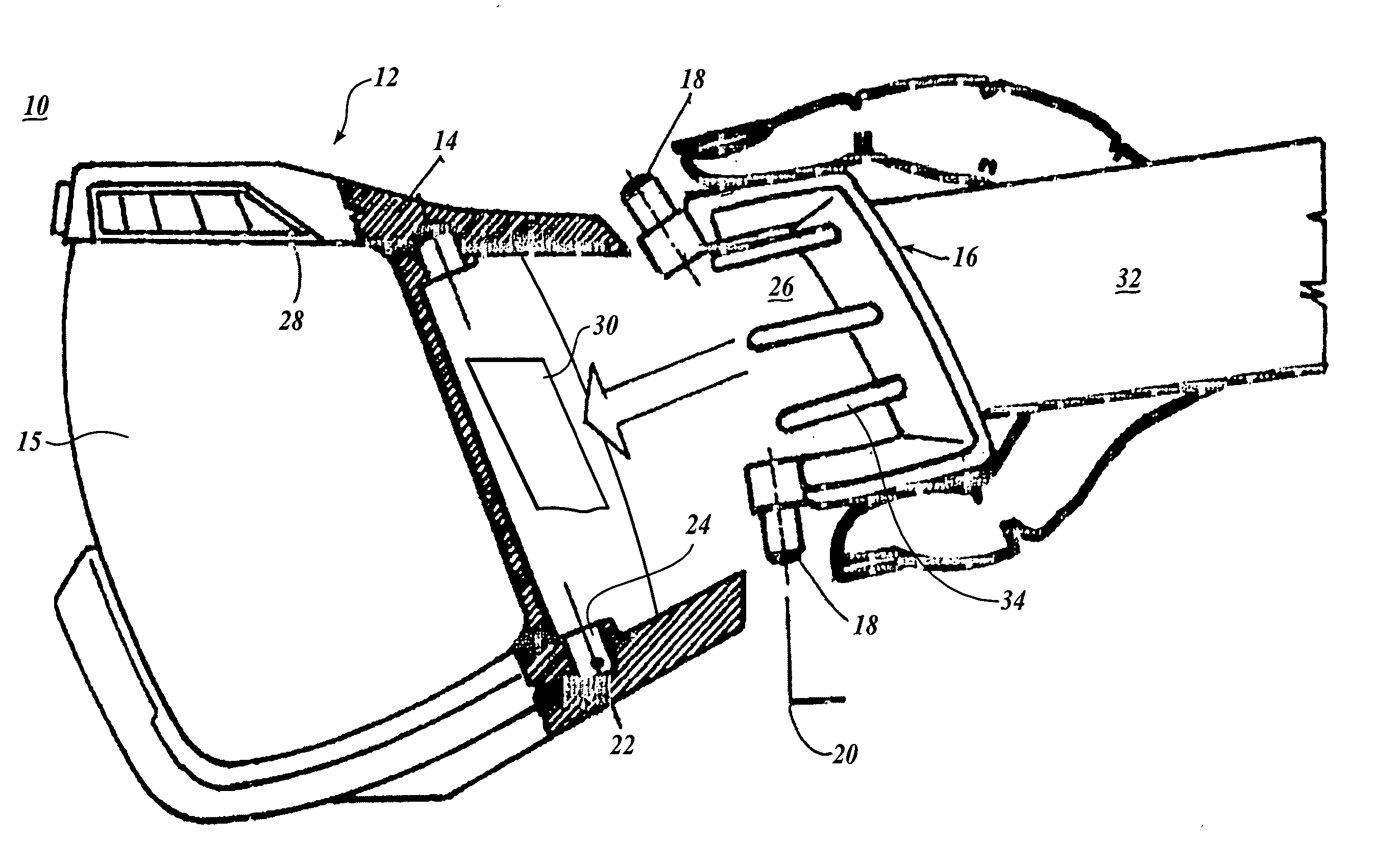
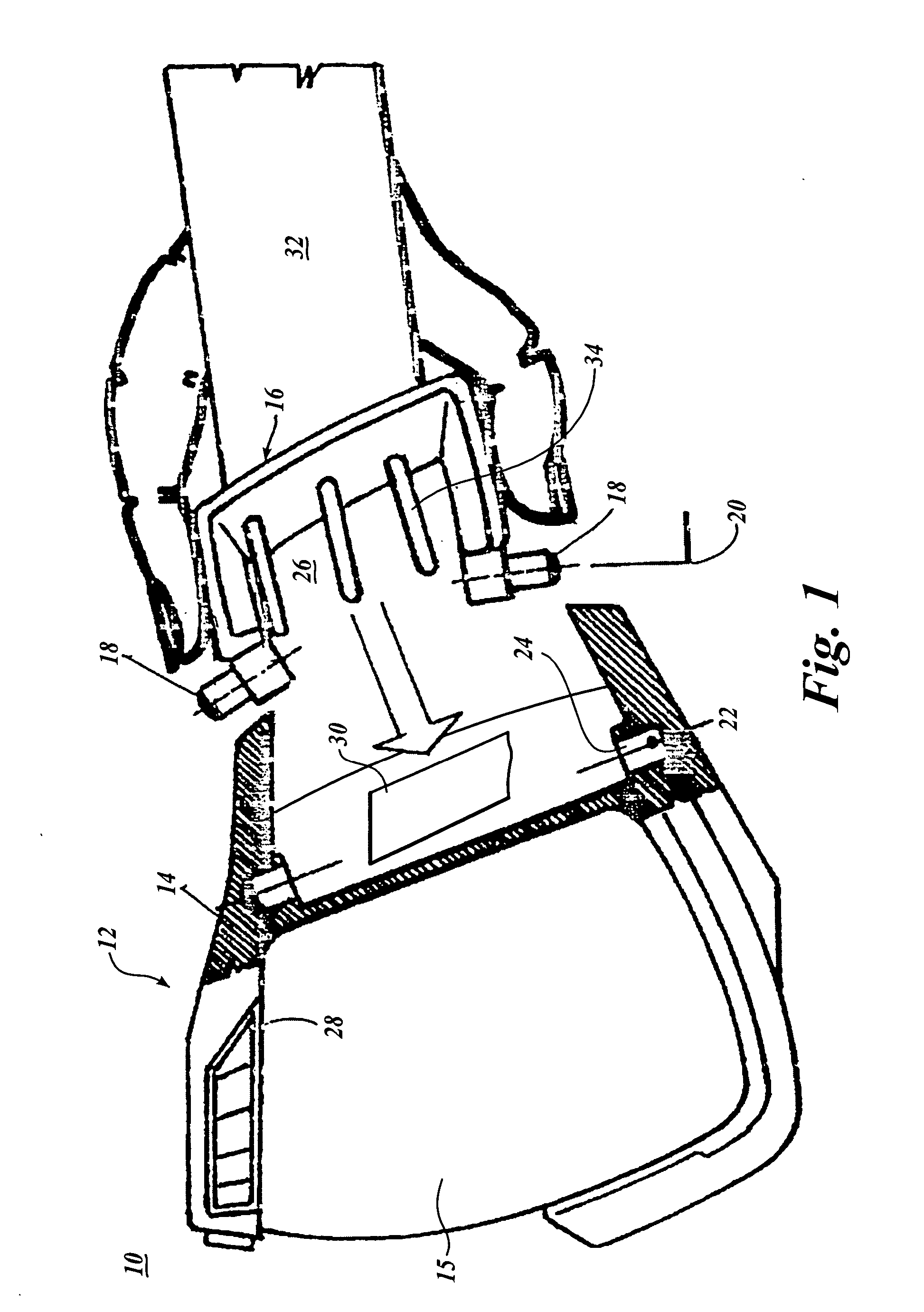
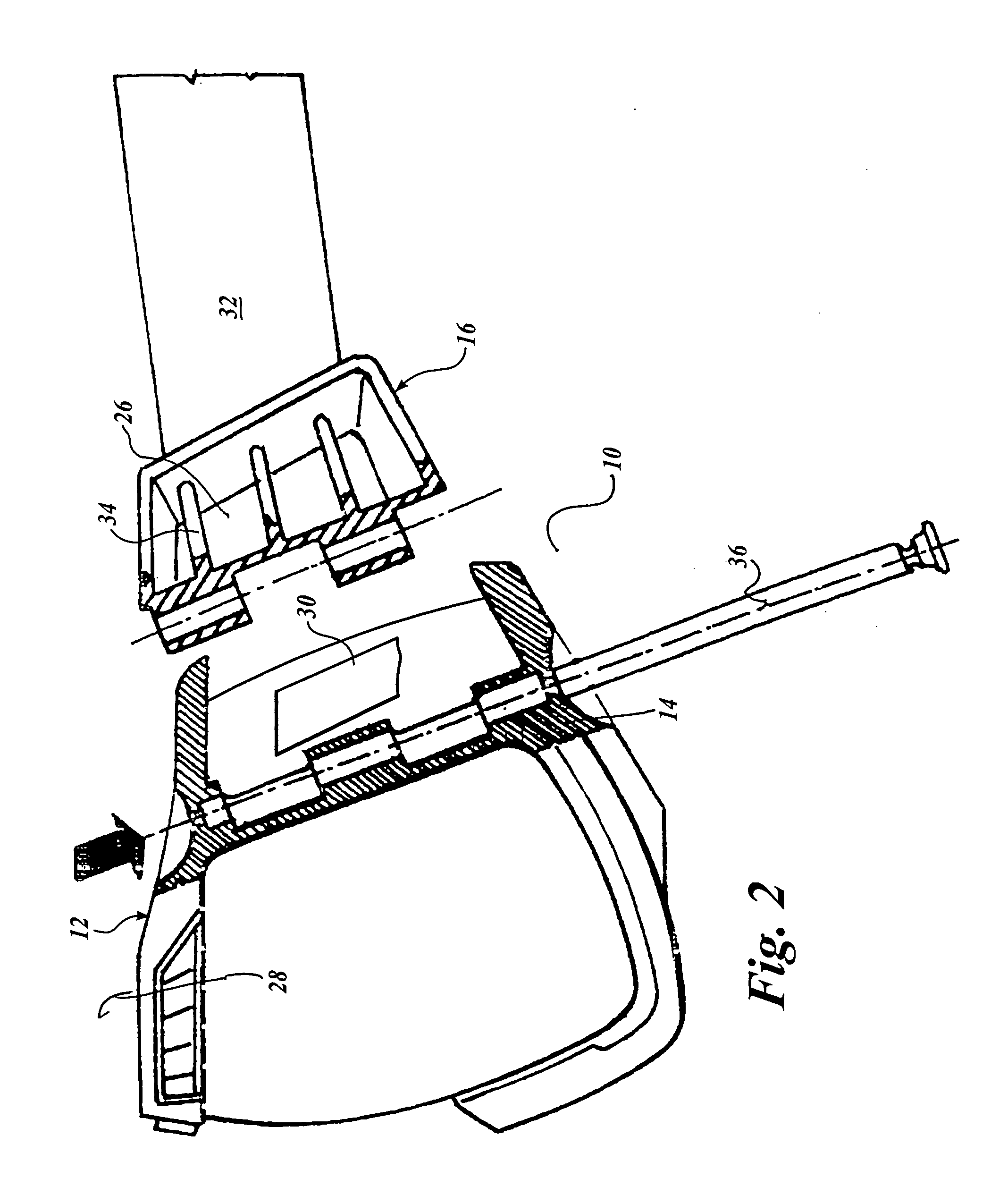
[0026] Referring now to the drawings, FIGS. 1-4 depict the various embodiments and engagements of the disclosed outrigger device 10 adapted for engagement with a goggle 12 at the goggle sidewalls 14.

[0027] As noted, FIG. 1 is a side exploded view of the goggle outrigger mounting system device 10 showing the outrigger 16 disengaged from its attachment to the sidewall 14 of the goggle 12. In this embodiment, engagement and disengagement is achieved by compressing the top and bottom walls of the outrigger 16 adjacent to the engagement end of the outrigger. The top and bottom walls are by default formed to position two pins 18 in positions where their pin axis 20 is aligned with a cavity axis 22 running between two receiving cavities 24 formed in the goggle sidewall 14. Compressing the top and bottom walls allows the pins 18 to be disengaged from a position where the pin axis 20 and cavity axis 22 are inline with the pins engaged, to a disengaged position where the outrigger 16 may be ...


PUM


Abstract

A goggle (12) having removable / replaceable outriggers (16) conveniently detachably engaged with the sidewalls (14) of the goggles. The outriggers (16) have an aperture (26) in communication with a venting aperture (30) communicating through the sidewall (14) to the eye cavity (28). Pins (18) project from flexible / compressible top and bottom walls of the outrigger (16) to engage within receiving cavities (24) formed in the goggle sidewalls (14).

Description

CROSS-REFERENCE TO RELATED APPLICATION [0001] This application claims the benefit of U.S. Provisional Patent Application No. 60 / 538,912, filed Jan. 23, 2004. This application is a continuation-in-part of U.S. patent application Ser. No. 10 / 695,055, filed Oct. 27, 2003, incorporated herein by reference. The present application is also a continuation-in-part of U.S. patent application Ser. No. 10 / 763,361, filed Jan. 23, 2004, incorporated herein by reference.BACKGROUND OF THE INVENTION [0002] 1. Field of the Invention [0003] The present invention relates to engagement of protective eyewear on the head of a user. More particularly it relates to an outrigger based system of mounting for goggles which renders the elastic strap or other means of engagement of the goggle removable from the goggle. Further, the outrigger being removable allows the user to adjust the aerodynamic design of the aperture communicating through the outrigger to fit the task at hand. The rotationally engaged outri...

Claims


Application Information

Patent Timeline
Patent Type & Authority Applications(United States)
IPC IPC(8): A61F9/02
CPCA61F9/025A61F9/028A61F9/027
Inventor HUSSEY, PATRICK P.
Owner K 2 CORP
Learn More