Pipe liners and method of lining pipes

a pipe and pipe lining technology, applied in the direction of pipes/joints/fittings, ceramic shaping apparatus, manufacturing tools, etc., can solve the problems of tube to evert, all the aforesaid methods have certain drawbacks, and the installation of the system can be costly

Inactive Publication Date: 2005-09-08
APPLIED FELTS +1
View PDF9 Cites 22 Cited by
  • Summary
  • Abstract
  • Description
  • Claims
  • Application Information

AI Technical Summary

Benefits of technology

[0037] According to another aspect of the present invention, the coe

Problems solved by technology

Moreover, fluid pressure is employed to move the tube comprising the coating and the resin impregnated tubular member along the passageway, and thus cause the tube to evert.
However, all the aforesaid methods have certain drawbacks.
This system can be costly to install and set-up times can be significant.
Moreover, damage to the liner during drag-in insertion is a major problem, as is the inherent friction between the outer surface of the liner, i.e. the coating of the tubular member, and the surface of the passageway.
This friction contributes to the likelihood of damage occurring to the liner during the insertion.
Any damage caused to the liner can lead to the liner being rendered inoperable, increasing the time and costs of the lining process, as the damaged liner is removed and a new liner inserted.
Nevertheless, friction considerations remain a major problem, particularly the liner-on-liner friction, or more particularly, coating-on-coating friction, which becomes a major factor during eversion, even though liner-on-passageway friction, or more particularly, coating-on-passageway friction, remains a consideration.
The application of oil is undesirable as it has both negative cost and environmental implications, and is generally a messy process, particularly when the oil is applied by spray.
Moreover, the oil will circulate in the eversion fluid of a typical hot-cure water eversion system and can generate tar deposits which are found to be detrimental to the efficiency of the heat exchanger of the water heater.
In either case, the presence of oil to reduce the friction associated

Method used


Image

  • Pipe liners and method of lining pipes
  • Pipe liners and method of lining pipes

Examples


example 1

Modified Polymer

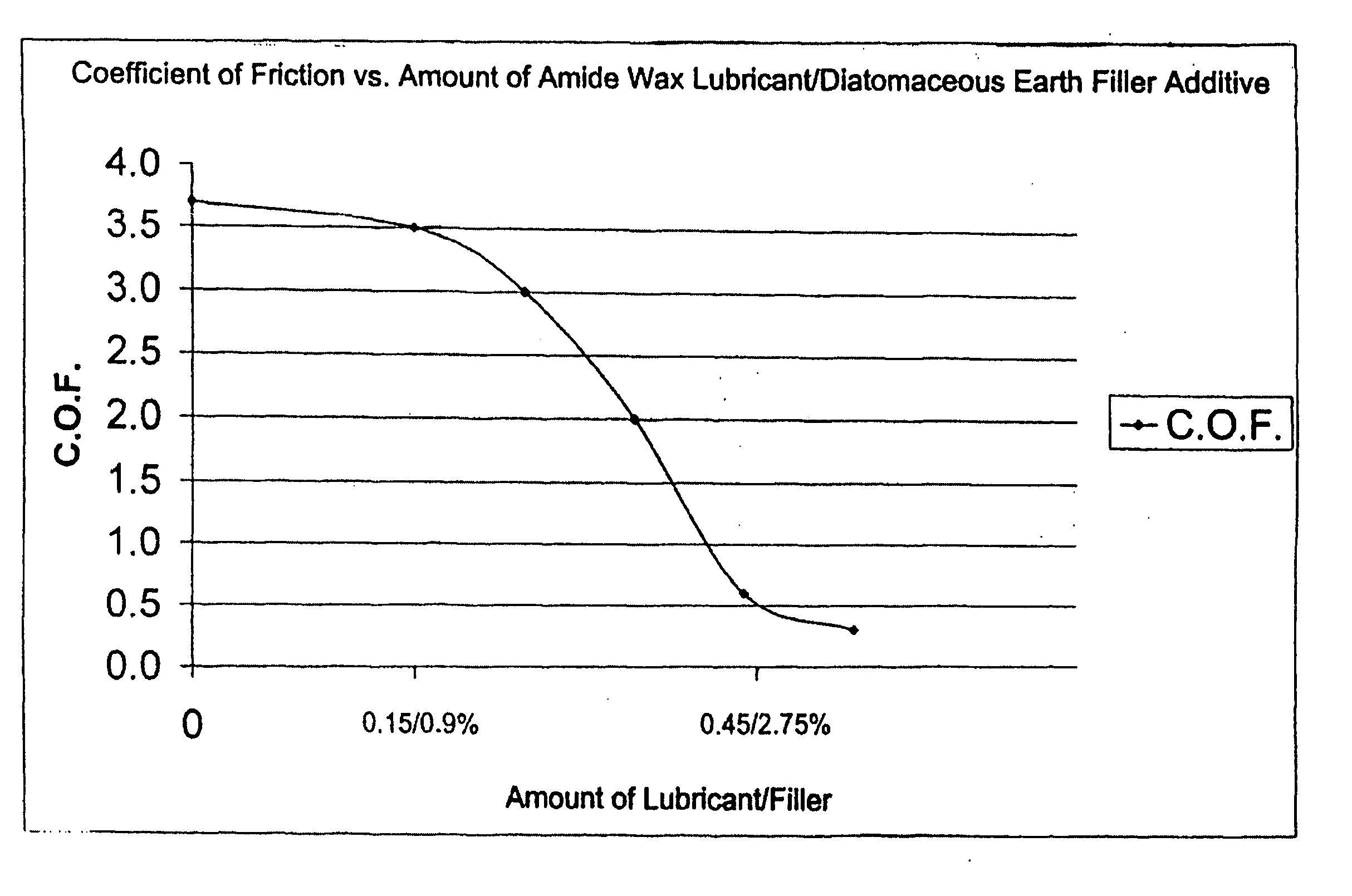
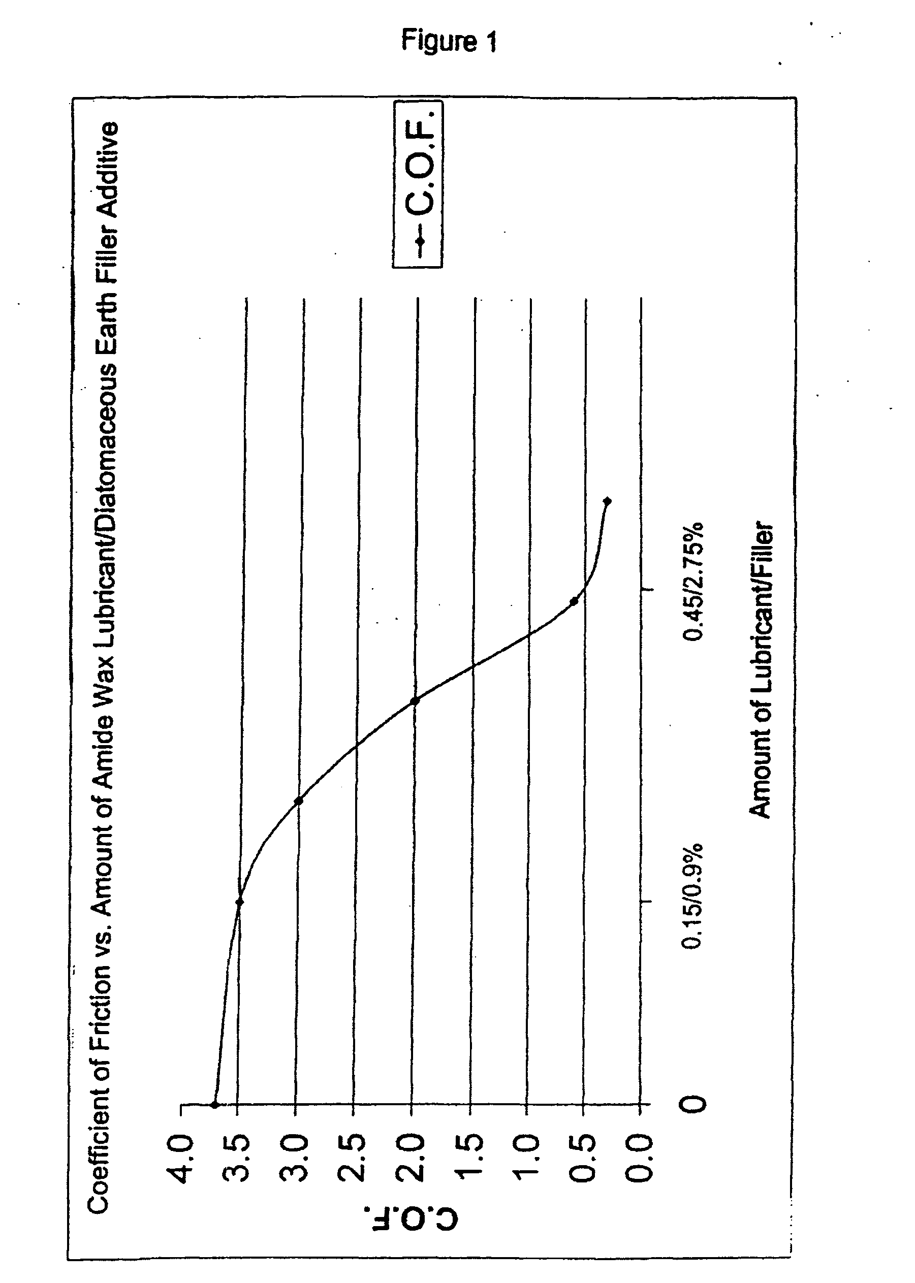
[0103] Various samples of Estane®, MC45DB1NAT021P, a thermoplastic polyurethane, was obtained from Noveon Europe B.V.B.A., Chausée de Wavre 1945, B-1160 Brussels, Belgium, wherein the thermoplastic polyurethane incorporated various levels of an amide wax lubricant additive, Glycolube VL, N—N′ ethylene bis stearamide (supplied by Lonza Group Ltd, Münchensteinerstrasse 38, Basel, Switzerland): 0.1%, 0.2%, 0.3%, 0.4%, 0.5% and 0.6% by weight with respect to the Estane®. Moreover, diatomaceous earth, Celite-Superfloss (supplied by Grupo Proquim, Centro Plaza Torre “B”, Piso 17 Av Francisco de Miranda Los Palos Grandes, Caracas 1060A—Venezuela) was dispersed in each sample as a filler / supporting additive: 0.5%, 1.0%, 1.5%, 2.0%, 2.5%, 3.0%, 3.5%, 4.0% by weight with respect to the Estane®. A further sample simply comprised Estane® MC45BD1NAT021P, i.e. with no Glycolube VL lubricant and no Celite-Superfloss filler additive.

[0104] The additives and filler / supporting addit...

example 2

Laboratory Coating and COF Measurement Set-Up

[0107] Two high gloss rollers of a ZKM600 laboratory melt coater [supplied by Kleinewefers Kunststoff Anlagen GmbH, Neuer Weg 24, D-47803 Krefeld, Germany] were heated to 170° C. and 180° C. for the back and front rollers, respectively. The coating speed was adjusted to 5 m / min.

[0108] A sample of 500 g of Estane® MC45DB1NAT021P was dried for 1 hour @ 110° C. in a tray. After cooling down to room temperature the thermoplastic polyurethane (TPU) was spread evenly between the two running rollers of the ZKM600 melt coater. The back roller ran at 4 m / min, the front roller at 5 m / min [friction ratio 20%].

[0109] The 500 g pre-dried Estane® MC45DB1NAT021P was left for at least 5 min to melt between the running ZKM600 rollers at a gap width less than 500 μm and more than 200 μm.

[0110] The roller speed and temperature differentials facilitated that a film of molten Estane® MC45DB1NAT021P formed on the front roller. During melting of the TPU the...


PUM

PropertyMeasurementUnit
Fractionaaaaaaaaaa
Fractionaaaaaaaaaa
Percent by massaaaaaaaaaa

Abstract

Provided herein are exemplary embodiments of novel and nonobvious liners, methods of lining passageways or pipelines using said liners, and uses of said liners. In one embodiment of the present invention, the liner comprises a resin absorbent material and a substantially impermeable coating. The substantially impermeable coating includes a modified polymer including a polymer having at least one additive incorporated thereto; wherein the dynamic coefficient of friction of the modified polymer is lower than the coefficient of friction of the polymer

Description

CROSS-REFERENCE TO RELATED APPLICATIONS [0001] This application claims the benefit of priority to UK Application Number 0403472.4, filed Feb. 17, 2004 and U.S. Application No. 60 / 552,177, filed on Mar. 10, 2004, the entire disclosure of each is hereby incorporated by reference as if set forth at length herein.STATEMENT REGARDING FEDERALLY SPONSORED RESEARCH OR DEVELOPMENT [0002] Not applicable REFERENCE OF A “MICROFICHE APPENDIX”[0003] Not applicable BACKGROUND OF THE INVENTION [0004] 1. Field of Invention [0005] The present invention relates, generally, to liners for pipes or passageways, such as underground passageways, and to methods of lining such passageways. More particularly, the invention relates to liners suitable for use in the cured in-situ or cured in position method of passageway lining. [0006] 2. Brief Description of the Prior Art [0007] The cured in-situ method of lining passageways has proven to be a very successful method over the years and a considerable improvemen...

Claims


Application Information

Patent Timeline
IPC IPC(8): B29C31/00F16L55/16
CPCF16L55/1656
Inventor BLADES, DAVID JOHNWIESSNER, ROBERT JAN
Owner APPLIED FELTS
Why Eureka
Try Eureka