Feed roller unit and conveyance apparatus

a technology of conveyancing apparatus and feed roller, which is applied in the direction of transportation and packaging, thin material processing, article separation, etc., can solve the problems of large conveyancing force applied to sheets, and achieve the effect of reducing the total conveyancing rate, reducing the starting and increasing the startup time of rotating the feed roller

Inactive Publication Date: 2005-09-08
BROTHER KOGYO KK
View PDF3 Cites 33 Cited by
  • Summary
  • Abstract
  • Description
  • Claims
  • Application Information

AI Technical Summary

Benefits of technology

[0007] In the related art, it is impossible to take measures against such a large conveyance force applied at the beginning of conveyance. The best measure to be taken is to increase the startup time of rotating the feed roller to thereby release the accumulated driving force gradually. However, when the startup time of rotating the feed roller is increased, the total conveyance rate of the sheets is lowered. Thus, in the case of a printer or the like, the lowered conveyance rate goes against the trend to increase the speed of image formation.
[0008] It is therefore one of objects of the present invention to provide a feed roller unit which can suppress a large conveyance force applied to sheets the moment a feed roller begins to rotate so that a multi feed of the sheets can be prevented reliably, and conveyance apparatus having the feed roller unit.

Problems solved by technology

However, it has been proved that a large conveyance force is applied to the sheets the moment the feed roller begins to rotate.

Method used


Image

  • Feed roller unit and conveyance apparatus
  • Feed roller unit and conveyance apparatus
  • Feed roller unit and conveyance apparatus

Examples


Embodiment Construction

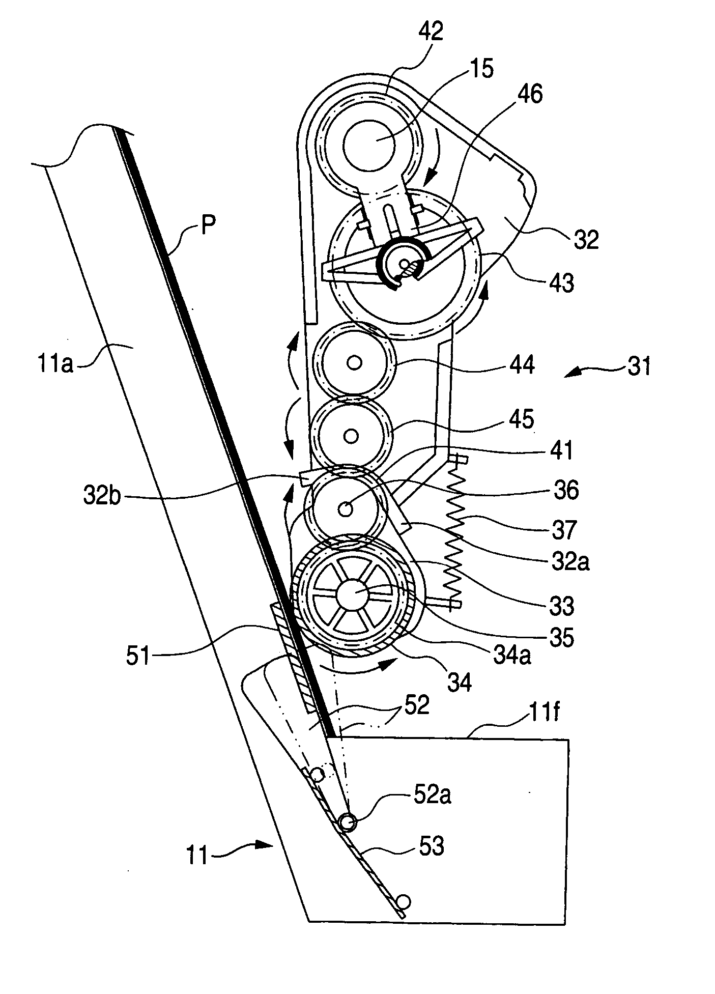
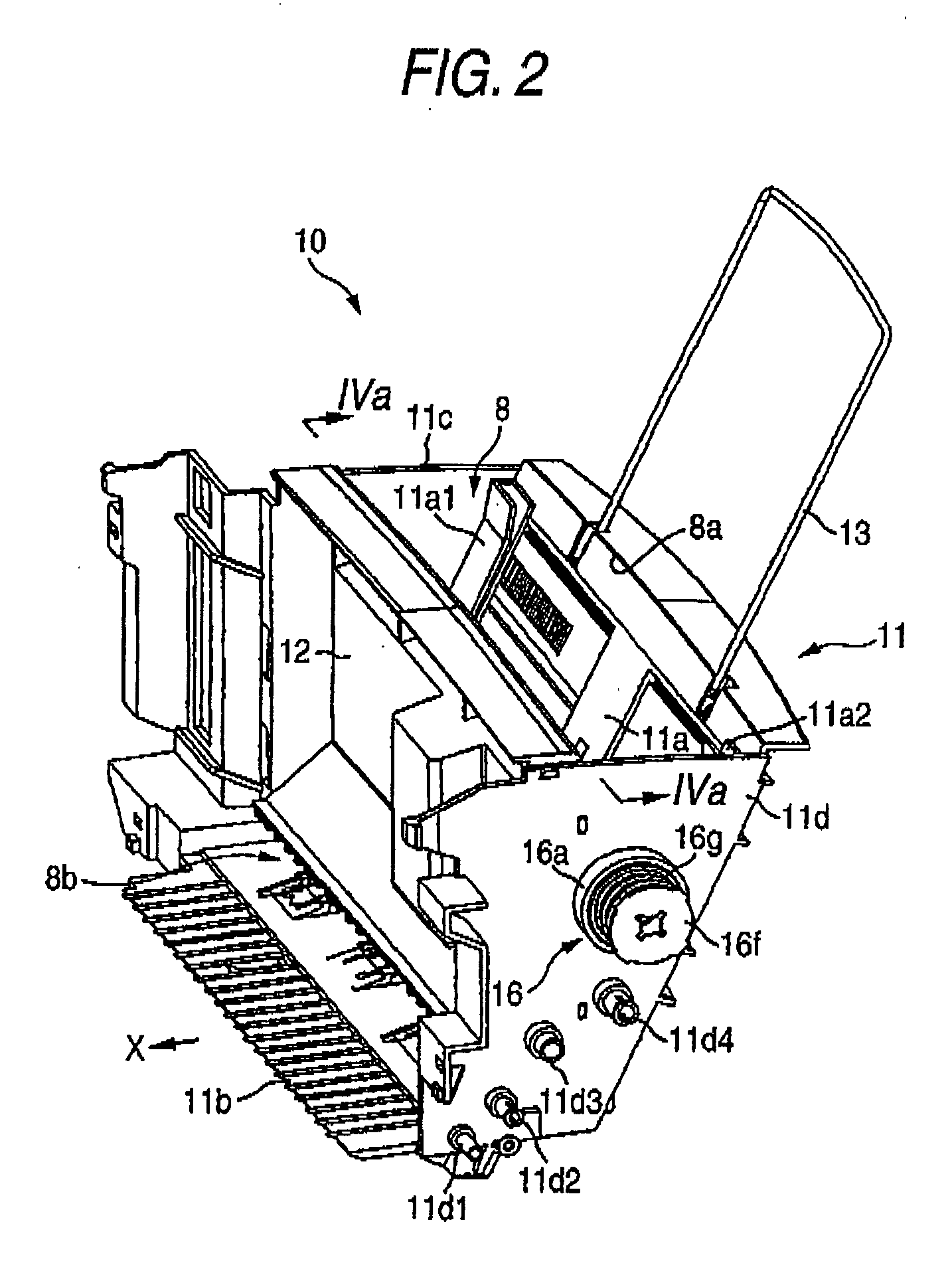
[0029] A preferred embodiment of the invention will be described below with reference to the accompanying drawings. The following description will be made using so-called inclined-feed type paper feed apparatus 10 (corresponding to conveyance apparatus according to the invention) in which a loading plate 11a (see FIG. 2) serving as a tray is disposed with a slope, by way of example. Needless to say, the invention can be also applied to so-called bottom-feed type paper feed apparatus in which a tray is disposed horizontally.

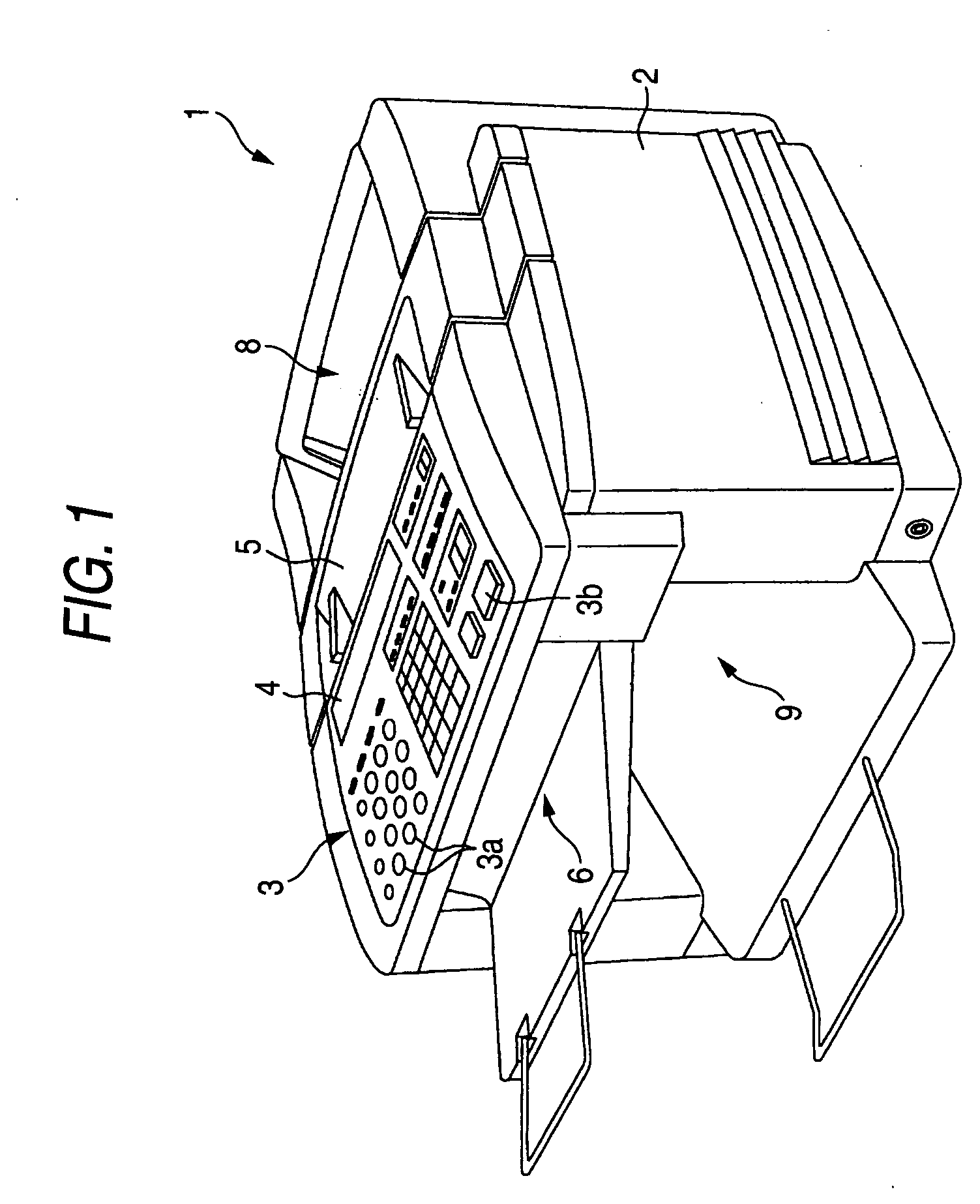
[0030]FIG. 1 is a perspective view of the external appearance of multifunctional peripheral apparatus 1 mounted with the paper feed apparatus 10 (see FIG. 2) according to an embodiment of the invention. The multifunctional peripheral apparatus 1 has various functions such as a facsimile function, a printer function, a scanner function, a copying function and a video function.

[0031] As shown in FIG. 1, the multifunction peripheral apparatus 1 has an apparatus bod...


PUM


Abstract

A feed roller unit comprises: a feed roller that abuts against a topmost sheet of a stack of sheets, and rotates to convey the topmost sheet in a conveyance direction, the feed roller being provided to be displaceable in a direction reverse to the conveyance direction while rolling on the topmost sheet; a driving force transmission unit that transmits a driving force generated by a driving source to the feed roller to rotate the feed roller; and an urging unit that provides an urging force to the feed roller in a direction to suppress the displacement of the feed roller.

Description

BACKGROUND OF THE INVENTION [0001] 1. Field of the Invention [0002] The present invention relates to a feed roller unit having a feed roller which can abut against a topmost sheet of a stack of sheets, and rotate to separate the top sheet from the other sheets and convey the top sheet in a specific conveyance direction, and conveyance apparatus having the feed roller unit. [0003] 2. Description of the Related Art [0004] There has been heretofore considered a feed roller unit having a feed roller which can abut against a top sheet of a stack of sheets, and rotate to separate the top sheet from the other sheets and convey the top sheet in a specific conveyance direction, and a driving force transmission unit for transmitting a driving force generated by a driving source to the feed roller so as to rotate the feed roller. In such a feed roller unit, the driving force generated by the driving source is transmitted to the feed roller through the driving force transmission unit so as to r...

Claims


Application Information

Patent Timeline
Patent Type & Authority Applications(United States)
IPC IPC(8): B65H3/52B65H3/06B65H5/00
CPCB65H3/0669B65H3/0684B65H2403/732B65H2403/531B65H2403/481
Inventor ASADA, TETSUO
Owner BROTHER KOGYO KK
Why Eureka
Try Eureka