
Plasma Spray Method
a technology of plasma and spraying, applied in chemical vapor deposition coating, inorganic chemistry, metallic material coating process, etc., can solve the problems of high cost, inability or only possible, unsuitable precursors, etc., and achieve the effect of reducing the conveying ra
- Summary
- Abstract
- Description
- Claims
- Application Information
AI Technical Summary
Benefits of technology
Problems solved by technology
Method used
Image

Examples
Embodiment Construction
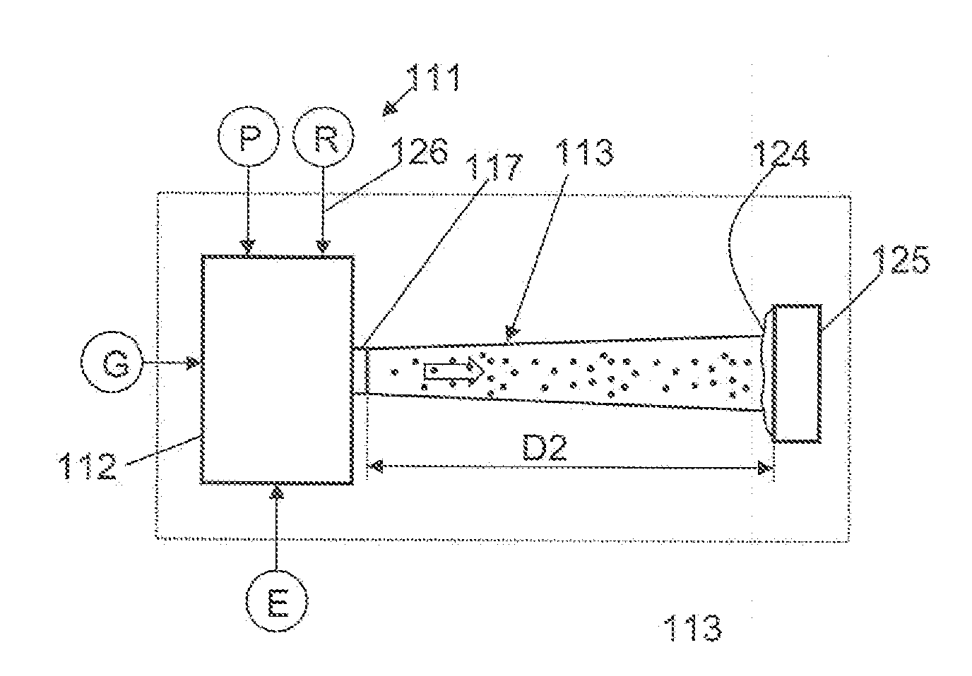
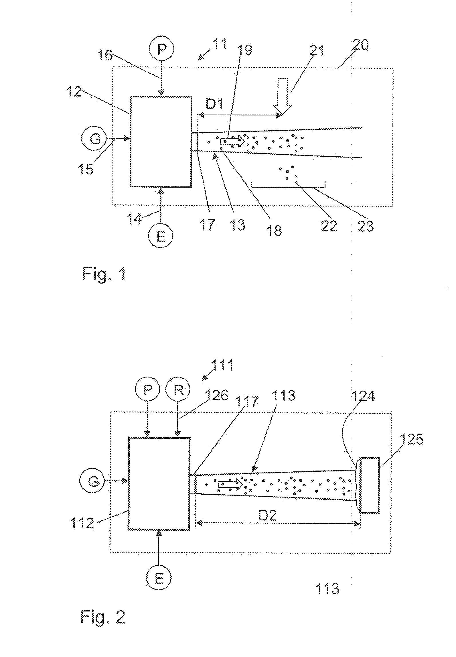
[0029]In accordance with FIG. 1, a plasma spray apparatus 11 suitable for carrying out a method in accordance with the invention has a plasma generator 12 known per se and having a plasma torch, not shown in more detail, for producing a plasma. A process jet 13 is generated in a manner known per se from a starting material P, a process gas mixture G and electrical energy E using the plasma generator 12. The feeding of these components E, G and P is symbolized by the arrows 14, 15, 16 in FIG. 1. The generated plasma jet 13 exits the plasma generator through an outlet nozzle 17 and transports the starting material P in the form of the plasma jet 13 in which material particles 18 are dispersed in a plasma. This transport is symbolized by an arrow 19.
[0030]The process gas G for the production of the plasma is preferably a mixture of inert gases, in particular a mixture of argon, hydrogen and helium.
[0031]The plasma spray apparatus 11 is arranged in a process chamber 20 in which a define...
PUM
| Property | Measurement | Unit |
|---|---|---|
| pressure | aaaaa | aaaaa |
| pressure | aaaaa | aaaaa |
| grain size | aaaaa | aaaaa |
Abstract
Description
Claims
Application Information