Appliance latch having a rotating latch hook mounted on a linear slide

a technology of latch hook and linear slide, which is applied in the field of latching mechanism for doors, can solve the problems of increasing the required height of the latch hook and the difficulty of using injection molded thermoplastic to implement the lever, and achieve the effect of being ready to implemen

Active Publication Date: 2005-09-08
ILLINOIS TOOL WORKS INC
View PDF17 Cites 91 Cited by
  • Summary
  • Abstract
  • Description
  • Claims
  • Application Information

AI Technical Summary

Benefits of technology

[0010] The present invention provides a latch in which a locking cam is held on a carriage that slides linearly, preferably under the force of a series of balanced springs. By eliminating the need for a lever subject to high bending forces, the present invention provides a more compact design that may be readily implemented with injection-molded parts.
[0011] Specifically then, the present invention provides an appliance latch for retaining a strike and having a latch frame affixable to a portion of the appliance, for example, the door or appliance housing. A carriage slideably held by the latch frame moves along a line substantially parallel to an axis along which the latch receives the strike. At least one spring biases the carriage along this line in the direction from which the latch receives the strike. A rotating hook is supported by the carriage to move with the carriage and to rotate about an axis perpendicular to the line. The rotating hook rotates to capture a portion of the strike in a capture position when the strike enters the hook opening, and rotates to release the strike in a release position when the strike exits the hook opening. A catch holds the carriage in a first position along the line with the spring in a high state of compression when the rotating hook is in the release position and releases the carriage in a second position along the line with the spring in a lower state of compression when the rotating hook is in the capture position. In this way, energy stored in the spring when opening the latch is returned to aid in closing the latch.

Problems solved by technology

The lever in this design provides for a relatively narrow latch but increases the required height of the latch because of the necessary length of the lever and the outboard position of the spring.
The lever is subject to significant bending forces making it difficult to implement the lever using injection molded thermoplastic, a material that is otherwise desirable in this application.

Method used


Image

  • Appliance latch having a rotating latch hook mounted on a linear slide
  • Appliance latch having a rotating latch hook mounted on a linear slide
  • Appliance latch having a rotating latch hook mounted on a linear slide

Examples


Embodiment Construction

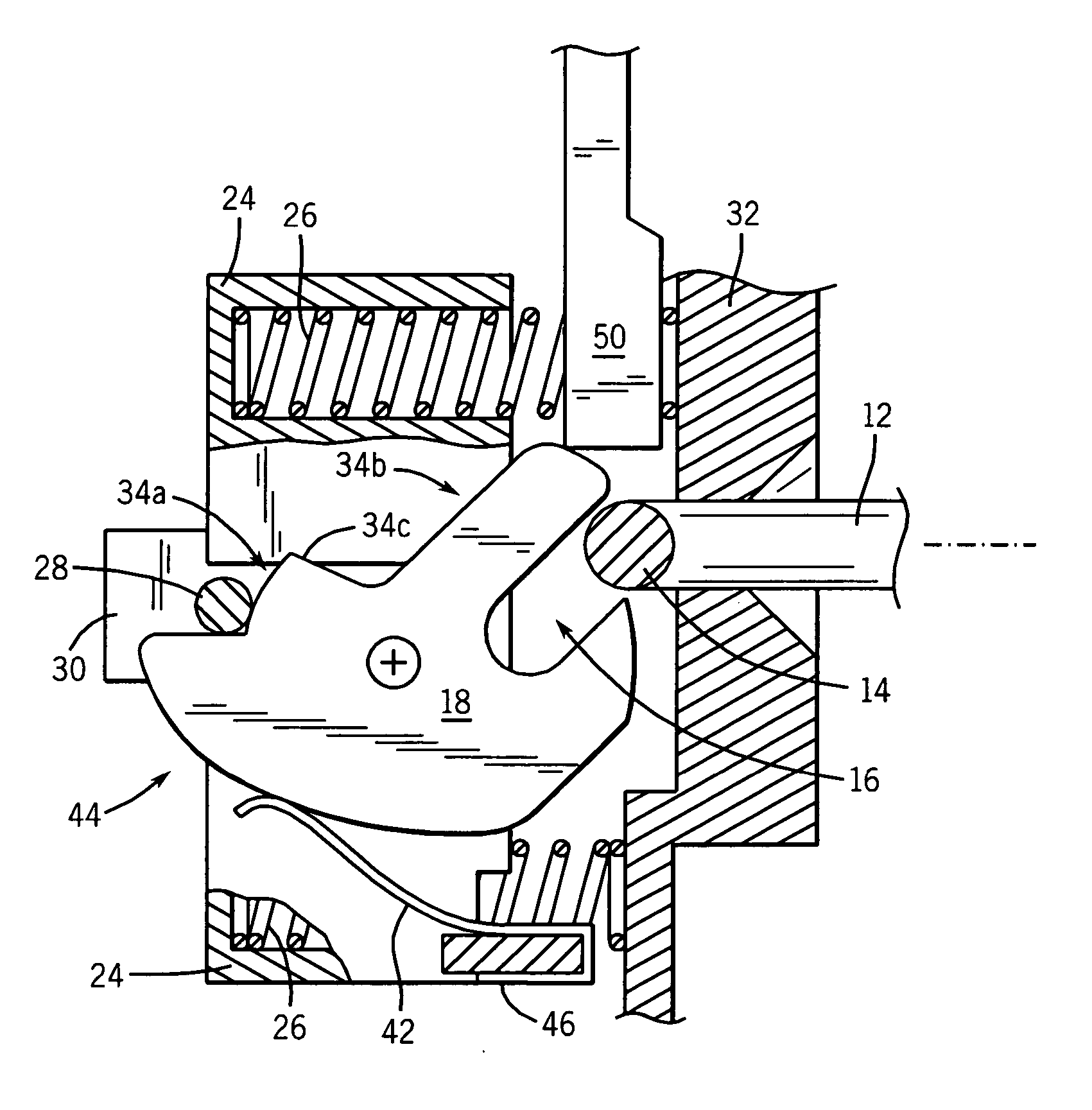
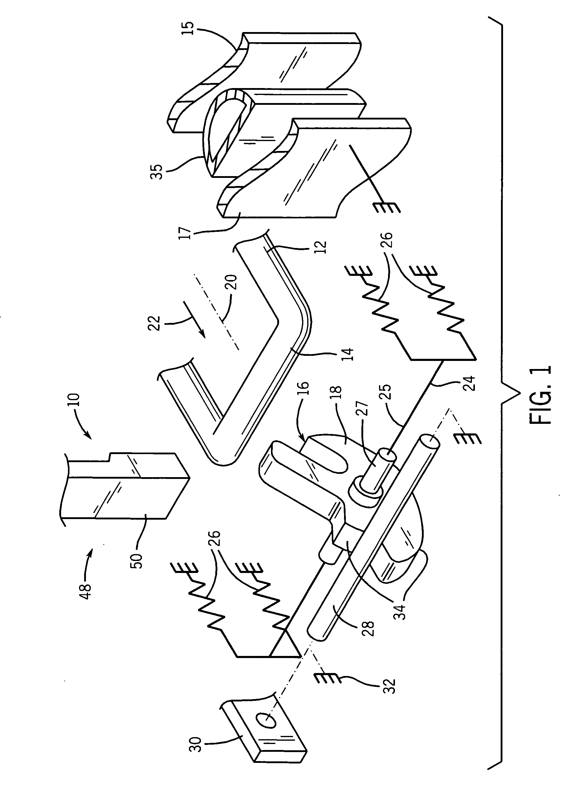
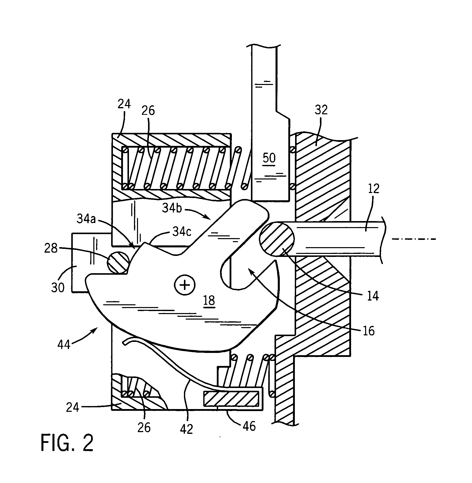
[0040] Referring now to FIG. 1, an appliance latch 10 of the present invention works with a strike 12, in this case, a U-shaped rod having a laterally extending strike bar 14. The strike 12, may be attached to a first portion 15 of an appliance, for example the appliance door, to be received by the appliance latch 10 attached to a second portion 17 of the appliance, for example, the appliance housing against which the door is closed.

[0041] The strike bar 14 of the strike 12 may engage a hook opening 16 of a rotating hook 18. The rotating hook 18 rotates on axle 27 about an axis 25 generally perpendicular to axis 20 and may receive the strike along an axis 20 in a direction 22.

[0042] The rotating hook 18 is mounted to a linear carriage 24 of the appliance latch 10. The linear carriage 24 is supported on a plurality of springs 26 to move in a line substantially along axis 20. The springs 26, which may be helical compression springs, urge the linear carriage 24 along direction 22.

[0...


PUM


Abstract

An appliance door latch provides a rotating hook supported on a linear carriage that may move along a line toward and away from a strike. A release of the strike from the rotating hook requires a compression of springs biasing the linear carriage which are then retained in a compressed state by a catch surface on the rotating hook. Re-engagement of the strike with the rotating hook releases the catch surface, causing the springs to pull the rotating hook and strike inward to aid in compressing a door gasket or the like.

Description

CROSS-REFERENCE TO RELATED APPLICATIONS [0001] This application claims the benefit of provisional Patent Application 60 / 550,526 filed Mar. 5, 2004 hereby incorporated by reference.STATEMENT REGARDING FEDERALLY SPONSORED RESEARCH OR DEVELOPMENT [0002] -- BACKGROUND OF THE INVENTION [0003] The present invention relates to a latching mechanism for doors on household appliances and particularly to latching mechanisms that provide assistance in compressing a door gasket or the like. [0004] Appliances such as dishwashers and front-loading washing machines may have an access door with a gasket that must be compressed to seal water within a washing chamber. Small area, highly compliant gaskets may be sealed by pressure from the user during the closing the door. The gasket may then be held in a compressed state by a latch mechanism. [0005] Gaskets which require more force may be compressed by a latch mechanism having a lever operated by the user to engage a catch and draw the catch inward wi...

Claims


Application Information

Patent Timeline
Patent Type & Authority Applications(United States)
IPC IPC(8): E05C19/10
CPCA47L15/4259D06F37/42D06F39/14E05C19/024E05B17/0029E05C3/24E05C5/00E05B17/0025Y10T292/1037Y10T292/1049Y10T292/1047
Inventor HAPKE, KENYON A.SULIK, JAROD MICHAEL
Owner ILLINOIS TOOL WORKS INC
Why Eureka
Try Eureka