Flickering device for automobile wheel

a technology for flickering devices and automobile wheels, which is applied in fixed installation, lighting and heating apparatus, and support devices for lighting and heating, etc., can solve the problems of high cost of replacing used batteries with new ones, inconvenient recharging of rechargeable batteries, and limitations in design of conventional light emitting devices

Inactive Publication Date: 2005-09-08
CHO YONG - RAK
View PDF3 Cites 20 Cited by
  • Summary
  • Abstract
  • Description
  • Claims
  • Application Information

AI Technical Summary

Benefits of technology

[0011] Accordingly, the present invention has been made keeping in mind the above problems occurring in the prior art, and an object of the present invention is to provide a flicke

Problems solved by technology

In the case of flickering Light Emitting Diodes (LEDs) using a battery, a used battery must be replaced with a new battery, so that a high cost is incurred to replace the used battery with the new battery.
In contrast, in the case of using a rechargeable battery, the rechargeable battery must be charged using an external power source and a charger, so that the recharging of the rechargeable battery is inconvenient.
When these conventional light emitting devices are applied to the rollers of the inline skates, the structures in which the conventional light emitting devices are contained must be constructed in circular form to ensure the smooth rotation thereof, so that the conventional light emitting devices have limitations in d

Method used


Image

  • Flickering device for automobile wheel
  • Flickering device for automobile wheel
  • Flickering device for automobile wheel

Examples


Embodiment Construction

[0034] Reference now should be made to the drawings,.in which the same reference numerals are used throughout the different drawings to designate the same or similar components.

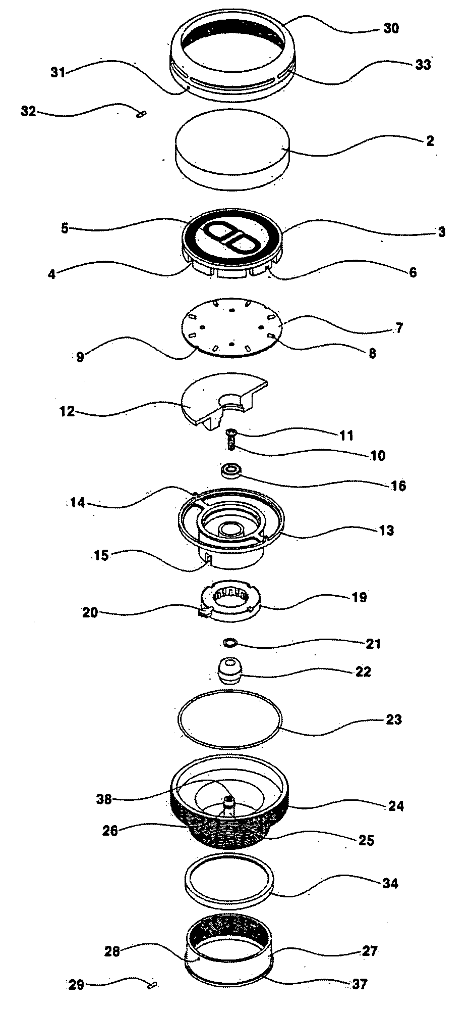
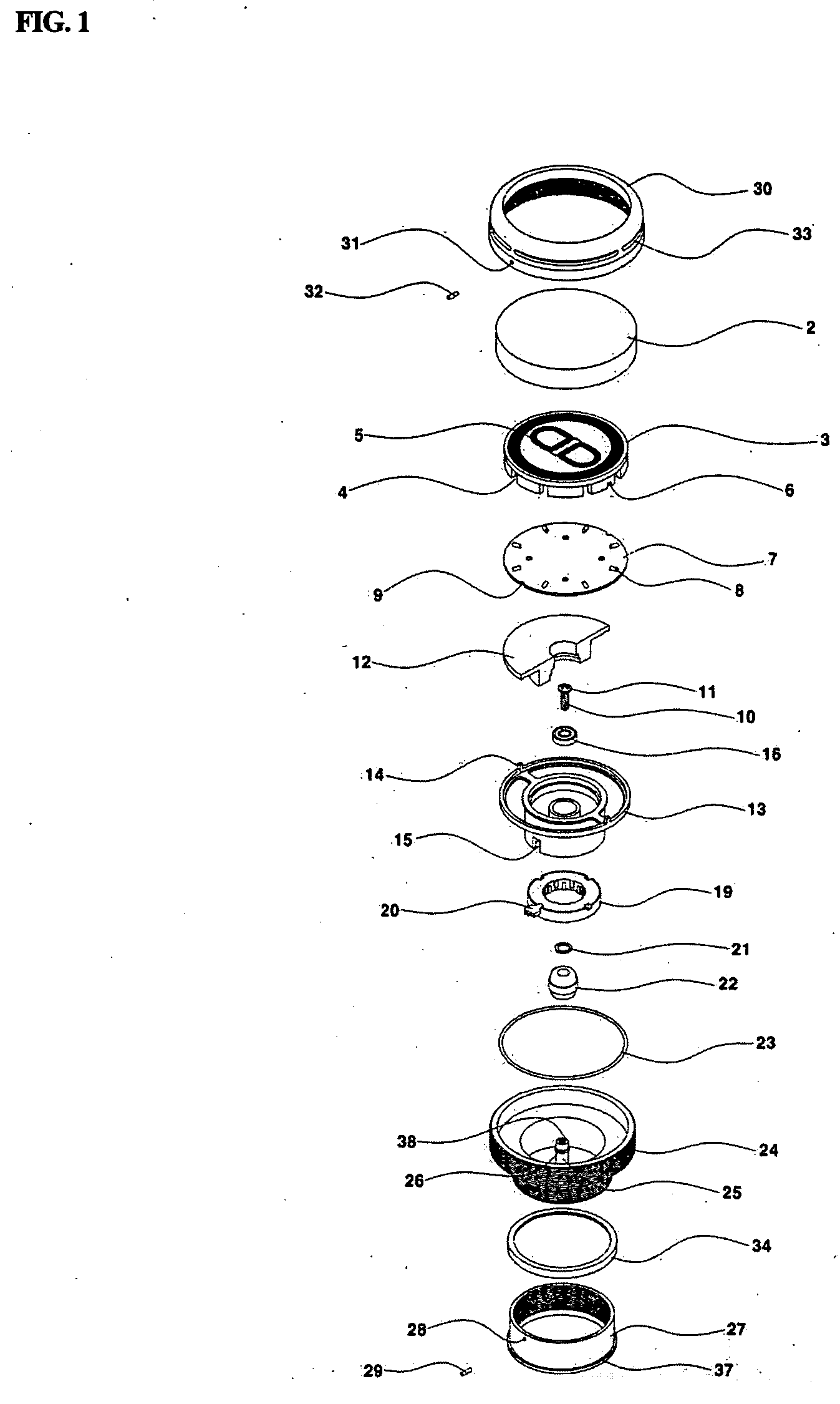
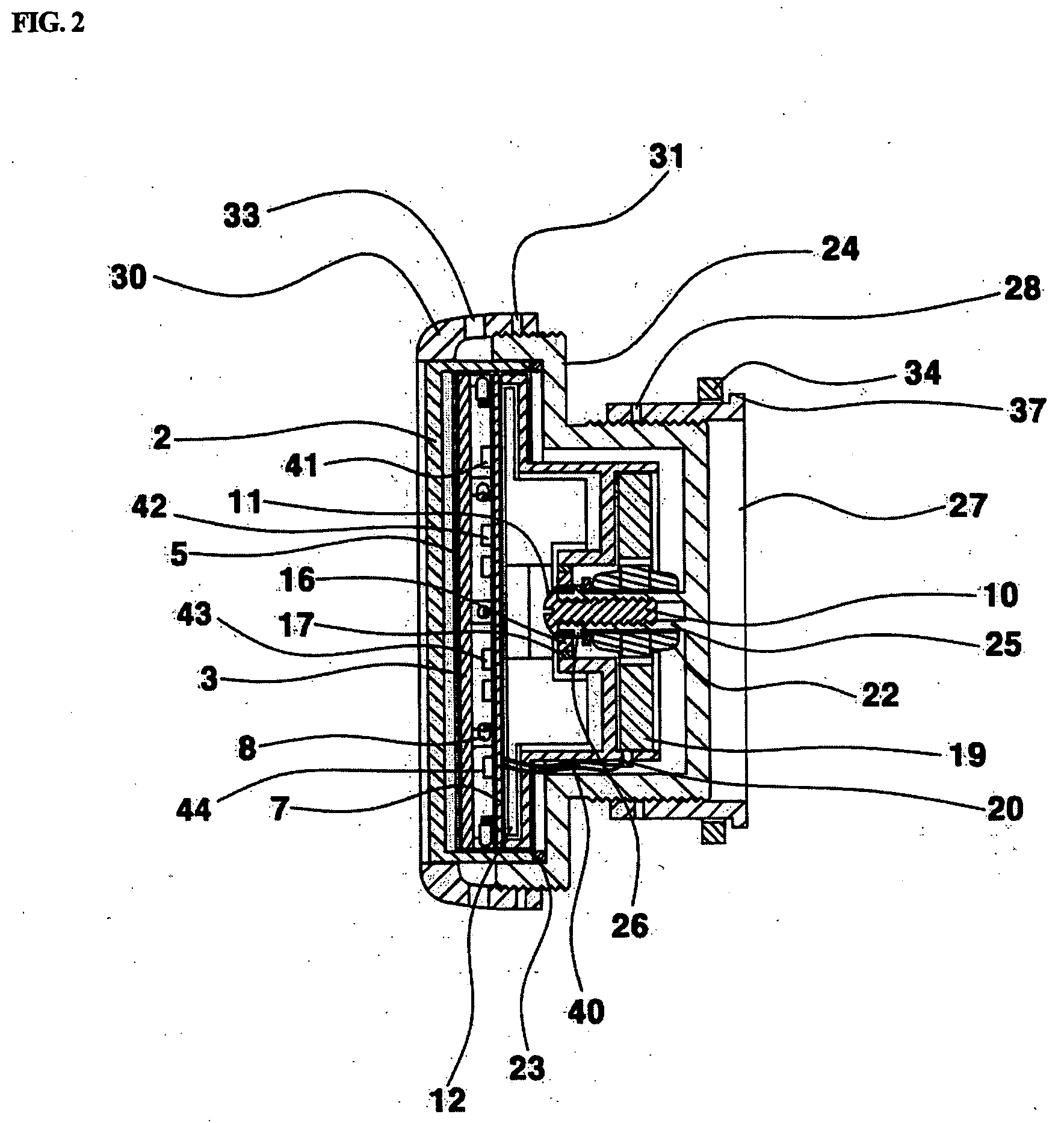
[0035] A flickering device 1 for an automobile wheel, in accordance with the present invention, includes:

[0036] a housing 24 capable of replacing an existing wheel hub, a coupling ring 27 inserted from the inside of an wheel hub 36 to the outside thereof to couple the housing 24 to a wheel 35, a deviation correction ring 13 engaged with the coupling ring 27 before combining with the housing 24 to compensate for a gap because the gap may occur between the housing 24 and the coupling ring 27 when the housing 24 and the coupling ring 27 are combined with each other through the wheel hub 36 in a screw manner while interposing the wheel 35 therebetween and the thickness of the wheel hub is constructed to be thinner than a standard thickness, a stopper protrusion 37 for stopping the deviation correction ring 34, ...


PUM


Abstract

Disclosed herein is a flickering device for an automobile wheel. The flickering device flickers using electromotive force, generated by the interaction between magnetic force and a coil unit as a rotating body rotates, as an electric power source. The flickering device has a circuit board. The circuit board includes a sensor for detecting power generated by rotation of a rotating shaft and a speed of an automobile; a timer adapted to receive signals from the sensor, count predetermined time and operate; a cadmium sulfide element for detecting brightness of light and supplying current; a control unit for controlling components; and LEDs adapted to be operated under the control of the control unit.

Description

CROSS REFERENCE RELATED TO THIS APPLICATION [0001] The applicant claims and requests a foreign priority, through the Paris Convention for the Protection of Industry Property, based on two patent applications each filed in the Republic of Korea (South Korea) with each filing date of Mar. 5, 2004 with the application number 10-2004-0015049, and Jun. 28, 2004 with the application number 20-2004-0018180, by the applicant. (See the Attached Declaration) BACKGROUND OF THE INVENTION [0002] 1. Field of the Invention [0003] The present invention relates to a flickering device for an automobile wheel, which is mounted on the hub of an automobile wheel, generates an electromotive force while the automobile wheel is rotated, and performs a flicker function using the electromotive force. [0004] 2. Description of the Related Art [0005] In the case of flickering Light Emitting Diodes (LEDs) using a battery, a used battery must be replaced with a new battery, so that a high cost is incurred to repl...

Claims


Application Information

Patent Timeline
IPC IPC(8): B60Q1/26
CPCB60Q1/326B60R13/005B60B7/0013B60B2900/931B60B7/14B60B2900/112B60B7/006
Inventor CHO, YONG RAK
Owner CHO YONG - RAK
Why Eureka
Try Eureka