Input device for pointing coordinates

a technology of input device and coordinates, which is applied in the direction of instruments, computing, electric digital data processing, etc., can solve the problems of poor operability of mouse operation with lifting, low degree of freedom of hands or fingers, and sound generation, and achieve low degree of freedom of hands and fingers. , the effect of high operability

Inactive Publication Date: 2007-05-03
HITACHI LTD
View PDF2 Cites 6 Cited by
  • Summary
  • Abstract
  • Description
  • Claims
  • Application Information

AI Technical Summary

Benefits of technology

[0036] It is therefore an object of this invention to provide a coordinate pointing device that has high operability for people having a low degree of freedom of hands and fingers and provide a mouse that does not impose burdens on a wrist and fingers.
[0038] According to this invention, it is possible to provide a coordinate pointing device that has high operability for people having a low degree of freedom of hands and fingers.

Problems solved by technology

With conventional techniques as described above, it is difficult for people with a low degree of freedom of hands or fingers such as physically handicapped people and patients of tenosynovitis, in particular, people having difficulty in bending fingers or gripping an object to lift the mouse.
The operation for moving the mouse with lifting has poor operability because the mouse is lifted and brought into contact with the plane.
Impact caused when the mouse comes into contact with the plane imposes burdens on a wrist and fingers of the user.
Moreover, sound generated when the mouse comes into contact with the plane is a nuisance for the user.
It is also difficult for those who have difficulty in bending fingers to push the select switch of the usual mouse.

Method used


Image

  • Input device for pointing coordinates
  • Input device for pointing coordinates
  • Input device for pointing coordinates

Examples


first embodiment

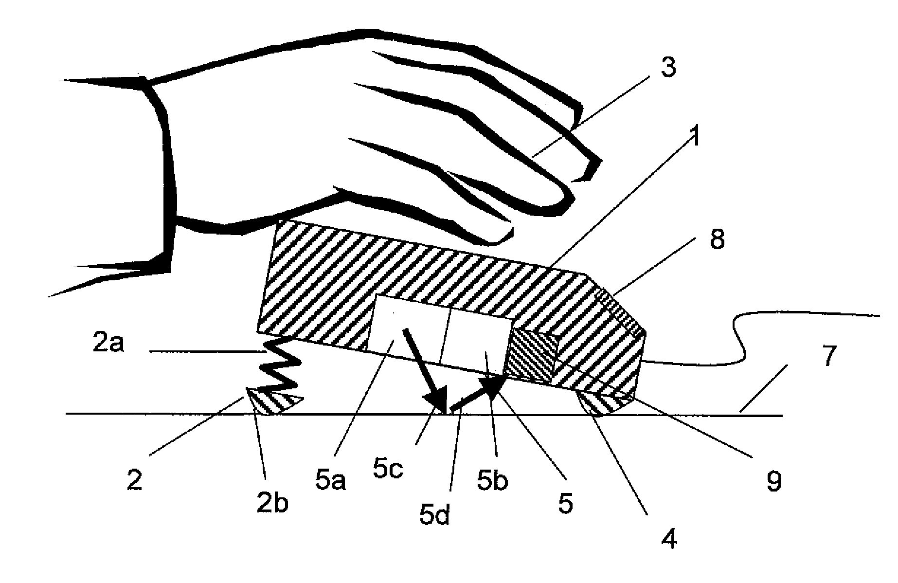
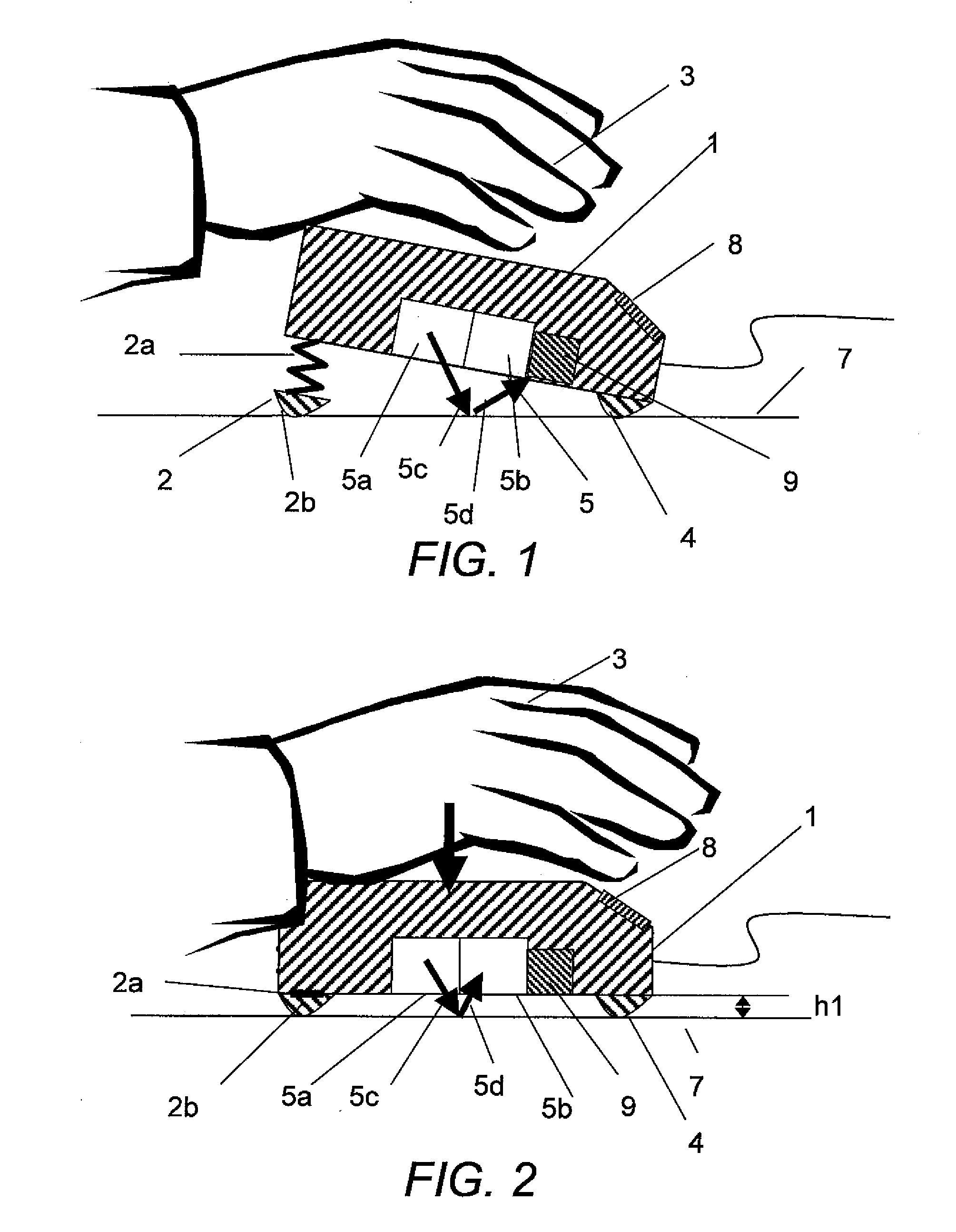
[0076] A first embodiment of this invention will be explained with reference to FIG. 1 to FIG. 3. In the first embodiment, a valid state and an invalid state of a detecting unit are switched by an elastic body in an optical mouse.

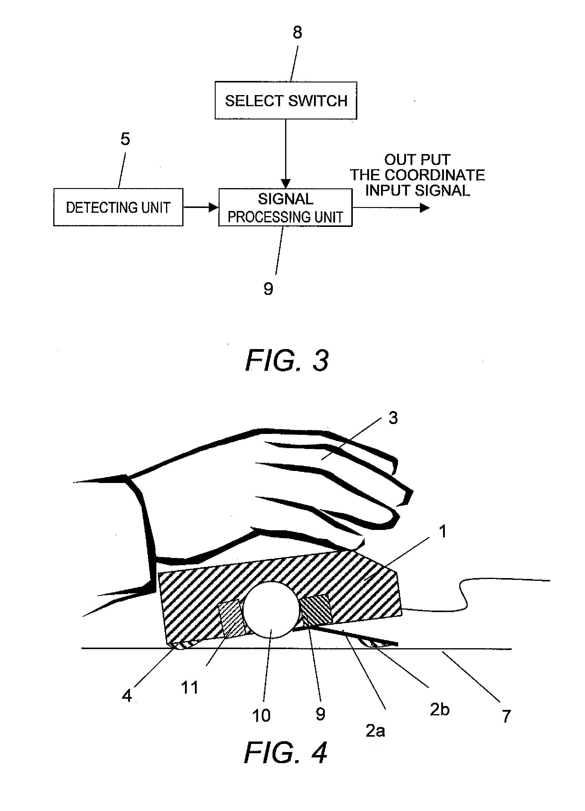
[0077] The optical mouse includes a housing 1, a detecting unit 5, a signal processing unit 9, and an interface unit.

[0078] The housing 1 has a size and a shape that make it easy for a user to grip the housing 1 with a hand. The housing 1 includes at least the detecting unit 5 in the inside thereof. The housing 1 has a bottom surface of a substantially planar shape opposed to a plane 7.

[0079] The housing 1 includes a sliding portion 4 in the front (hereinafter, when the user grips the mouse with a hand, a finger tip side is assumed to be the front) of the bottom surface. The housing 1 includes posture changing means 2 in the rear of the bottom surface. The posture changing means 2 includes a coil spring 2a, which is an elastic body, and a sliding portion...

second embodiment

[0095] A second embodiment of this invention will be explained with reference to FIG. 4 and FIG. 5. In the second embodiment, a valid state and an invalid state of a detecting unit are switched by an elastic body in a boll-type mouse.

[0096] The ball-type mouse includes a housing 1, a detecting unit 5, a signal processing unit 9, and an interface unit.

[0097] The housing 1 has a size and a shape that make it easy for a user to grip the housing 1 with a hand. The housing 1 includes at least the detecting unit 5 and the signal processing unit 9 in the inside thereof. The housing 1 has a bottom surface of a substantially planar shape opposed to a plane 7.

[0098] The housing 1 includes a sliding portion 4 in the rear of the bottom surface. The housing 1 includes posture changing means 2 in the front of the bottom surface. The posture changing means 2 includes a leaf spring 2a, which is an elastic body, and a sliding portion 2b and changes position of housing 1 against the plane 7 when a...

third embodiment

[0114] A third embodiment of this invention will be explained with reference to FIG. 6 and FIG. 7. In the third embodiment, a valid state and an invalid state of a detecting unit are switched by an elastic body in a foot mouse.

[0115] In the third embodiment, the mouse according to the second embodiment operated by the hand of the user is made operable by a foot 12 of the user. A structure according to the third embodiment is substantially identical with the structure according to the second embodiment. Components identical with those according to the second embodiment are denoted by the identical reference symbols and explanations thereof are omitted.

[0116] Since the user operates the mouse with the foot 12, the housing 1 has a size and a shape that make it easy for the user to operate the housing 1 with the foot 12.

[0117] As shown in FIG. 7, when a predetermined load is applied to the front of the ball-type mouse with a toe of the foot 12, the leaf spring 2a is compressed and th...


PUM


Abstract

Provided is a coordinate pointing device including a detecting unit for detecting movement of a main body of the coordinate pointing device, a signal processing unit for outputting a coordinate input signal based on information detected by the detecting unit, and a switching unit for switching a valid state in which the detecting unit detects the movement of the main body of the coordinate pointing device and an invalid state in which the detecting unit does not detect the movement of the main body.

Description

CLAIM OF PRIORITY [0001] The present application claims priority from Japanese patent application 2005-314679 filed on Oct. 28, 2005, the content of which is hereby incorporated by reference into this application. BACKGROUND OF THE INVENTION [0002] The present invention relates to a coordinate pointing device for inputting coordinates. [0003] As coordinate pointing devices, there are various forms such as a mouse, a trackball, a touch panel, a touch pad, a digitizer, and a joy stick. However, nowadays, the mouse is generally used because the mouse is excellent in operability that allows a user to operate the mouse intuitively in moving the mouse, usability due to a size, weight, and the like of the mouse itself, simplicity of a structure, and durability. [0004] The user moves the mouse on a plane by gripping a housing of the mouse with a hand. When the mouse is moved, a cursor on a screen of a host apparatus to which the mouse is connected moves. [0005] As the mouse, a ball-type mou...

Claims


Application Information

Patent Timeline
Patent Type & Authority Applications(United States)
IPC IPC(8): G09G5/08G06F3/0354
CPCG06F3/0334G06F3/03544
Inventor ISHIKAWA, TADAAKIHORII, YOUICHIHOSHINO, TAKESHI
Owner HITACHI LTD
Why Eureka
Try Eureka