

Bulk bag for dense materials
a technology of dense materials and bulk bags, applied in the direction of flexible containers, sacks, packaging, etc., can solve the problem that the construction of bulk bags of derby invention is not entirely successful in maintaining a rectangular configuration
- Summary
- Abstract
- Description
- Claims
- Application Information
AI Technical Summary
Problems solved by technology
Method used
Image

Examples
first embodiment
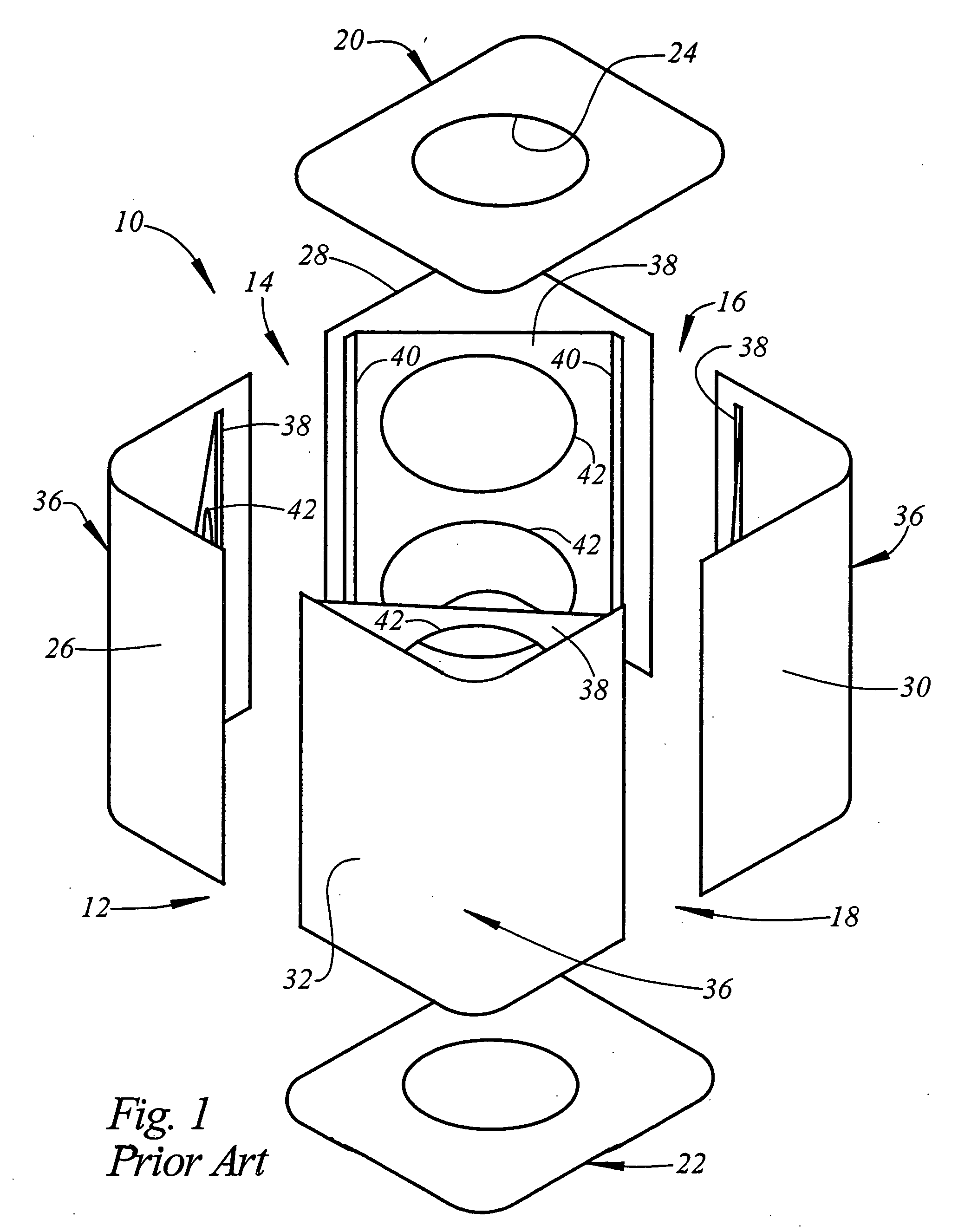
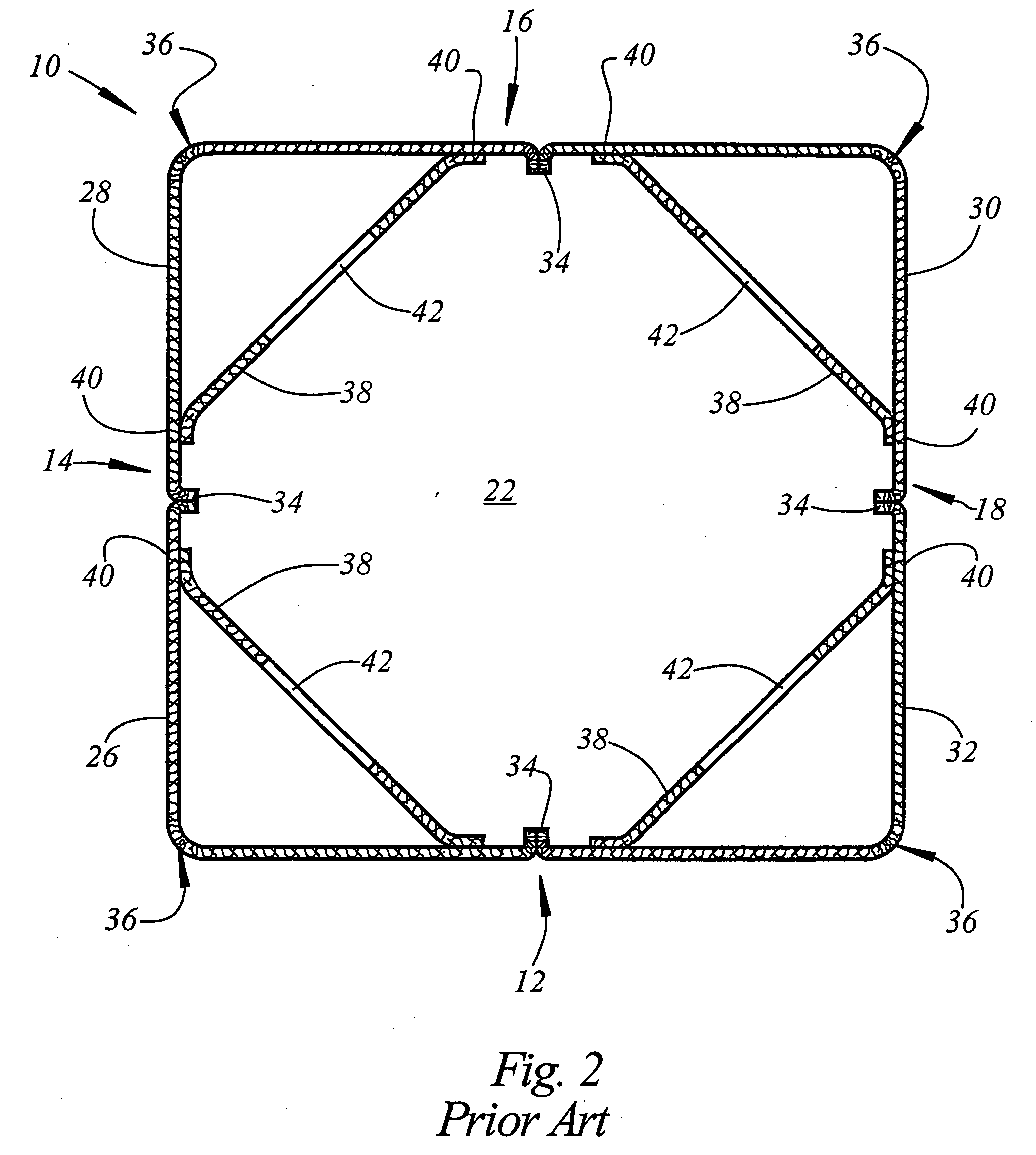
[0026] Referring now to FIG. 3, there is shown a bulk bag 110 comprising the present invention. The bulk bag 110 includes four side walls 112, 114, 116, and 118. The bulk bag 110 further includes a bottom wall 122 and may include a top wall, although open top bulk bags are known. The top wall and the bottom wall may be provided with an aperture which receives a fill spout in the case of the top wall or a discharge spout in the case of the bottom wall.
[0027] The side walls 112, 114, 116, and 118 of the bulk bag 110 are formed from four side panels 126, 128, 130, and 132. The side panels 126, 128, 130, and 132 are joined one to another at seams 134 each of which is located in a spaced apart relationship to the corners 136 of the bulk bag 110. In the embodiment of the invention illustrated in FIG. 3, the seams 134 are located at points equidistant from adjacent corners 136, however, other configurations can be used in the practice of the invention, if desired.
[0028] Each of the side p...
second embodiment
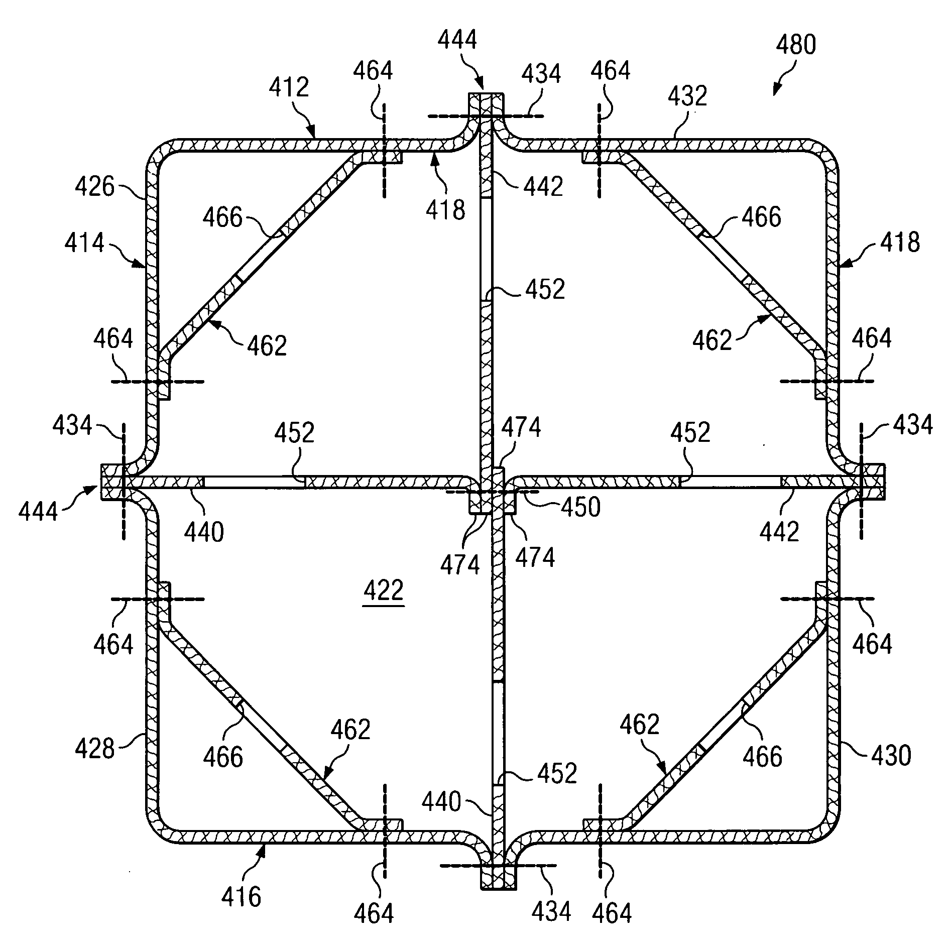
[0030] Referring now to FIG. 4, there is shown a bulk bag 210 comprising the present invention. The bulk bag 210 includes four side walls 212, 214, 216, and 218. The bulk bag 210 further includes a top wall and a bottom wall 222 either of which may be provided with an aperture which receives a fill spout in the case of the top wall or a discharge spout in the case of the bottom wall.
[0031] The side walls 212, 214, 216, and 218 of the bulk bag 210 are formed from six side panels 226, 227, 228, 230, 231, and 232. The side panels 226, 227, 228, 230, 231, and 232 are joined one to another at seams 234 each of which is located in a spaced apart relationship to the corners 236 of the bulk bag 210. In the embodiment of the invention illustrated in FIG. 4, the side walls 214 and 218 which include the panels 227 and 231, respectively, are relatively longer than the side walls 212 and 216.
[0032] Each of the side panels 226, 228, 230, and 232 is provided with a baffle 238. Each baffle 238 is ...
third embodiment
[0034] Referring to FIGS. 5 and 6, there is shown a bulk bag 310 comprising the present invention. The bulk bag 310 includes four side walls 312, 314, 316, and 318. The bulk bag 310 further includes a top wall and a bottom wall 322 either of which may be provided with an aperture which receives a fill spout in the case of the top wall or a discharge spout in the case of the bottom wall.
[0035] The side walls 312, 314, 316, and 318 of the bulk bag 310 are formed from four side panels 326, 328, 330, and 332. The side panels 326, 328, 330, and 332 are joined one to another at seams 334 each of which is located in a spaced apart relationship to the corners 336 of the bulk bag 310. In the embodiment of the invention illustrated in FIG. 5, the seams 334 are located at points equidistant from adjacent corners 336, however, other configurations can be used in the practice of the invention, if desired.
[0036] Each of the side panels 326, 328, 330, and 332 is provided with a baffle 338. Each b...
PUM
 Abstract
Description
Claims
Application Information