Controlled pressure fuel nozzle system

a fuel nozzle and controlled technology, applied in the direction of turbine/propulsion fuel valves, machines/engines, lighting and heating apparatus, etc., can solve the problems cumbersome multi-manifold fuel systems, and drooping speed of centralized staging fuel systems during acceleration

Active Publication Date: 2005-09-15
GENERAL ELECTRIC CO
View PDF12 Cites 44 Cited by
  • Summary
  • Abstract
  • Description
  • Claims
  • Application Information

AI Technical Summary

Problems solved by technology

These multi-manifold fuel systems are cumbersome and require many looped or bent fuel supply tubes of multiple shapes and sizes to feed the differential staged fuel nozzles.
Fuel systems with multiple centralized staging valves are expensive and engine designers are always strivi...

Method used


Image

  • Controlled pressure fuel nozzle system
  • Controlled pressure fuel nozzle system
  • Controlled pressure fuel nozzle system

Examples


Embodiment Construction

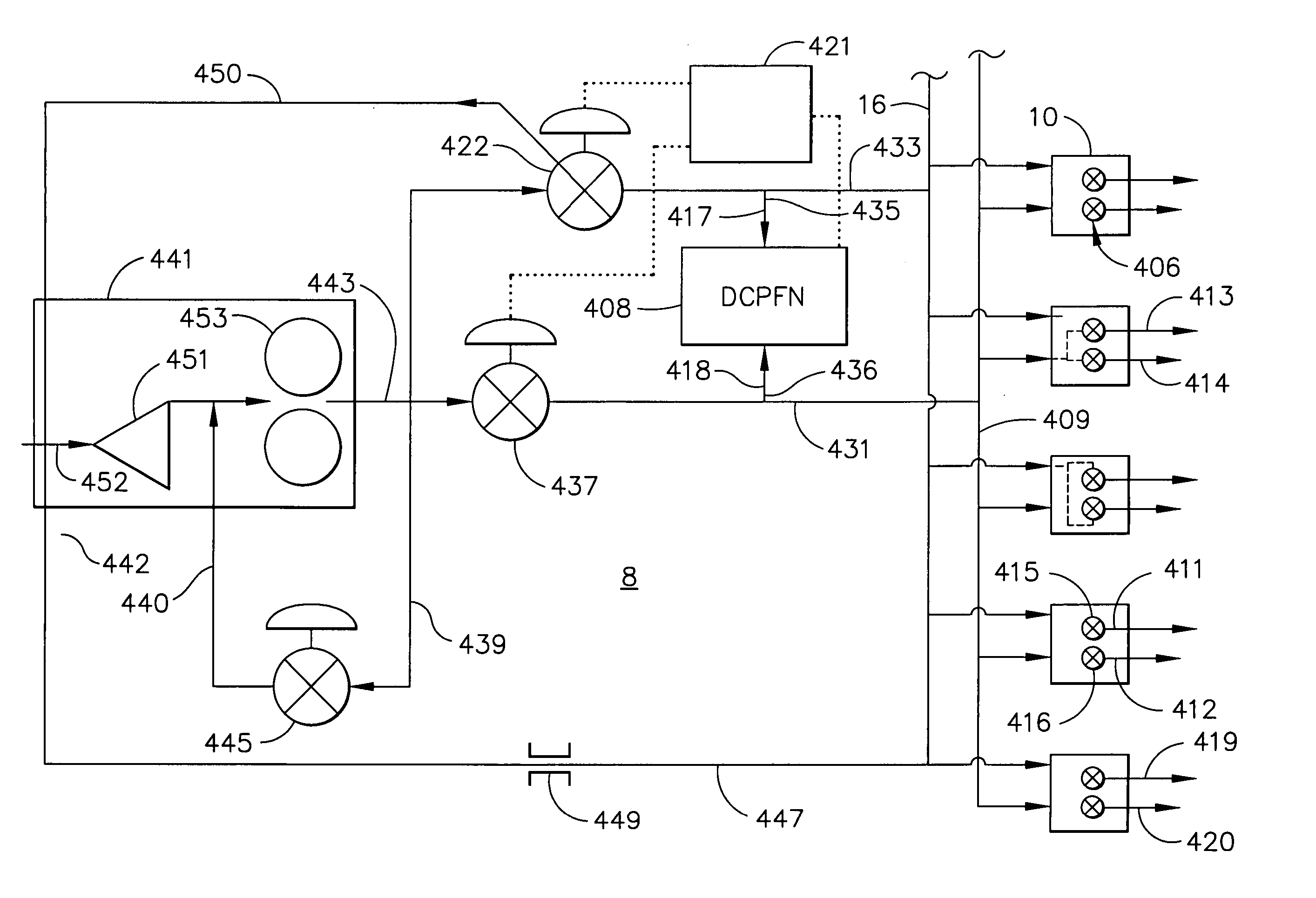
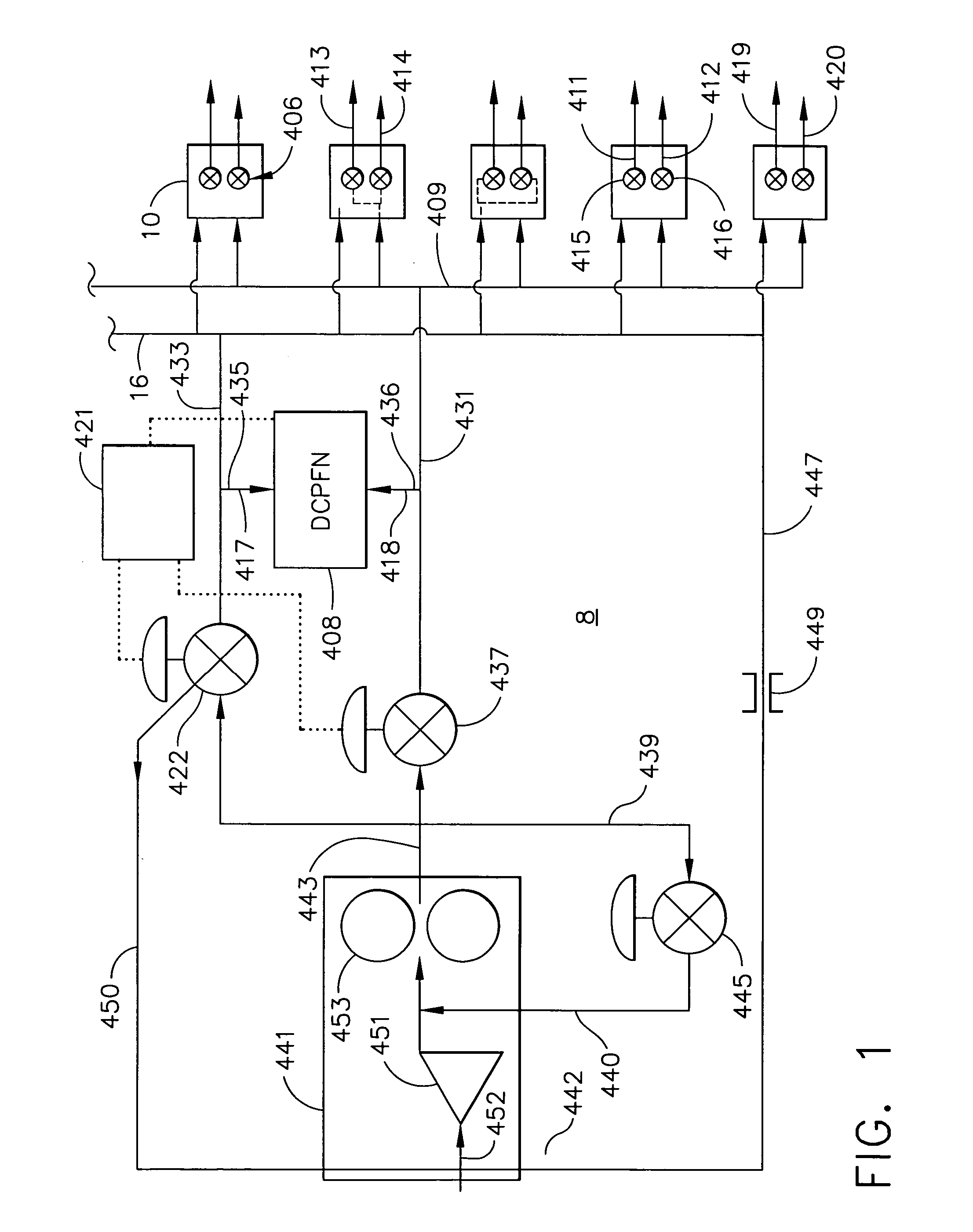
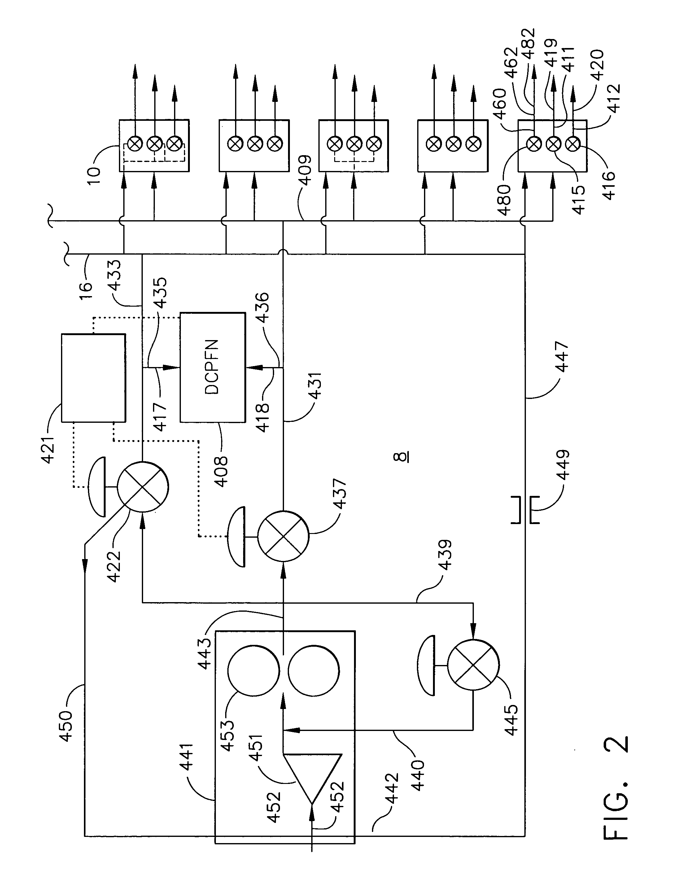
[0023] Schematically illustrated in FIG. 1 is an exemplary embodiment of a multi-staged gas turbine engine fuel supply system 8 that provides fuel to first and second staged fuel injection circuits 411 and 412 of each of a plurality of fuel injectors 10. Each of the first and second staged fuel injection circuits 411 and 412 has first and second fuel injection points 413 and 414. First and second fuel nozzle valves 415 and 416 are controllably connected to the first and second staged fuel injection circuits 411 and 412, respectively. A fuel supply circuit 431 includes a single fuel supply manifold 409 connected in fuel supplying relationship to all of the fuel nozzle valves 415 and 416. The first and second fuel nozzle valves 415 and 416 are operable to open at different first and second crack open pressures 419 and 420, respectively, as indicated by the different arrow lengths representing the different crack open pressures. All of the first and second fuel nozzle valves 415 and 41...


PUM


Abstract

A multi-staged gas turbine engine fuel supply system includes a plurality of fuel injectors and at least first and second staged fuel injection circuits in each of the fuel injectors. Each of the first and second staged fuel injection circuits includes first and second fuel injection points and at least first and second fuel nozzle valves operable to open at different first and second crack open pressures and controllably connected to the first and second staged fuel injection circuits, respectively. A single fuel supply manifold is connected to all of the fuel nozzle valves. A single fuel signal manifold is controllably connected to all of the first and second fuel nozzle valves. The fuel injector may have a valve housing with one of the first fuel nozzle valves and one of the second fuel nozzle valves contained therein.

Description

FIELD OF THE INVENTION [0001] The present invention relates generally to gas turbine engine combustor fuel systems and, more particularly, such fuel systems employing fuel staging. [0002] In order to lower emissions, gas turbine engines are using lean burning combustors which require turning on and off independent fuel circuits over a range of operating conditions including engine power level and environmental conditions. This is often referred to as fuel staging and is required to keep a local fuel / air ratio of the engine within a narrow range defined at its upper limit by NOx emissions and at its lower limit by a flame-out boundary. [0003] Current engines use multiple individually controlled centralized staging valves with multiple fuel supply manifolds which deliver fuel to the fuel nozzles. There is one fuel supply manifold for each stage, thus, each fuel nozzle has multiple fuel supply connections, one for each stage. In order to prevent coking fuel should be either drained fro...

Claims


Application Information

Patent Timeline
IPC IPC(8): F02C7/22F02C7/232F02C9/26F23R3/28F23R3/34
CPCF23R3/343
Inventor MYERS, WILLIAM JOSEPH JR.NG, THOMAS VANDERMANCINI, ALFRED ALBERTCOOPER, JAMES NEIL
Owner GENERAL ELECTRIC CO
Why Eureka
Try Eureka