Coupled baw resonator based duplexers

a duplexer and baw resonator technology, applied in piezoelectric/electrostrictive/magnetostrictive devices, piezoelectric/electrostriction/magnetostriction machines, electrical equipment, etc., can solve the problem of additional losses in the duplexer, the possibility of unbalanced-to-balance transformation, and the difficulty of achieving a device of high resonance frequency using this fabrication method

Active Publication Date: 2005-09-22
NOKIA CORP +1
View PDF11 Cites 47 Cited by
  • Summary
  • Abstract
  • Description
  • Claims
  • Application Information

AI Technical Summary

Benefits of technology

[0062] According to the present invention, the first coupled resonator device has a single-to-single configuration and the second coupled resonator device has a single-to-balance transformation.

Problems solved by technology

In general, it is difficult to achieve a device of high resonance frequency using this fabrication method.
Using such a structure, it is possible to perform this unbalanced-to-balanced transformation.
These coils not only cause additional losses in the duplexer, but also create other higher resonance frequencies, further degrading the overall out-of-band attenuation of a single-ended filter.
The problem with this approach is that any loss associated with the baluns at the antenna port will also cause losses in the Tx path.

Method used


Image

  • Coupled baw resonator based duplexers
  • Coupled baw resonator based duplexers
  • Coupled baw resonator based duplexers

Examples


Embodiment Construction

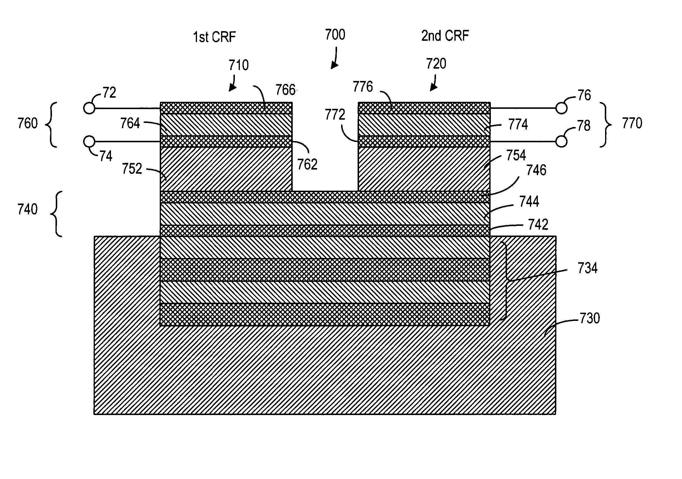
[0085] The duplexer, according to the present invention, is based on coupled BAW resonator devices. The coupled resonator device is shown in FIG. 10. The coupled resonator device 700 comprises a coupled resonator filter (CRF) 710 coupled to another CRF 720. As shown in FIG. 10, the resonator device 700 comprises a substrate 730, a lower resonator 740, a first delay 752, a second delay 754, a first upper resonator 760 and a second upper resonator 770. The lower resonator 740 comprises a bottom electrode 742, an upper electrode 746 and a piezoelectric layer 744 disposed between the electrodes 742 and 746. The first delay 752 and the second delay 754, which are separately disposed on top of the lower resonator 740, are composed of a plurality of layers of different dielectric materials. The structure of the first delay 752 and the second delay 754 can be SiO2 / W / SiO2, for example. The first upper resonator 760, which is disposed on top of the first delay 752, comprises a bottom electrod...


PUM


Abstract

A duplexer comprising a transmit resonator device and a receive resonator device for filtering transmit and receive signals. The resonator device has a first BAW resonator for generating an acoustic wave signal from an input electric signal, a first acoustic delay for delaying the acoustic wave signal, and an intermediate BAW resonator for receiving the delayed acoustic wave signal at one end and converting the delayed acoustic wave signal to an electric signal. Through electrical coupling, the electric signal also appears at another end of the intermediate BAW resonator for generating a further acoustic wave signal at the other end. The resonator further comprises a second delay for delaying the further acoustic wave signal, and a second BAW resonator for producing an output electric signal from the delayed further acoustic wave signal. The duplexer can be used in a transceiver in a mobile phone.

Description

FIELD OF THE INVENTION [0001] The present invention relates generally to bulk acoustic wave resonators and filters and, more particularly, to bulk acoustic wave baluns used in filters and duplexers. BACKGROUND OF THE INVENTION [0002] It is known that a bulk acoustic-wave (BAW) device is, in general, comprised of a piezoelectric layer sandwiched between two electronically conductive layers that serve as electrodes. When a radio frequency (RF) signal is applied across the device, it produces a mechanical wave in the piezoelectric layer. The fundamental resonance occurs when the wavelength of the mechanical wave is about twice the thickness of the piezoelectric layer. Although the resonant frequency of a BAW device also depends on other factors, the thickness of the piezoelectric layer is the predominant factor in determining the resonant frequency. As the thickness of the piezoelectric layer is reduced, the resonance frequency is increased. BAW devices have traditionally been fabricat...

Claims


Application Information

Patent Timeline
Patent Type & Authority Applications(United States)
IPC IPC(8): H03H7/42H03H9/54H03H9/58H03H9/60H03H9/70
CPCH03H7/42H03H9/706H03H9/589H03H9/584H03H9/58H03H9/60H03H9/70
Inventor ELLA, JUHAAIGNER, ROBERT
Owner NOKIA CORP
Why Eureka
Try Eureka