System and method for generating pseudorandom numbers

a pseudorandom number and system technology, applied in the field of pseudorandom number generation, can solve the problem of associated delay of each devi

Active Publication Date: 2005-09-22
TEXAS INSTR INC
View PDF7 Cites 82 Cited by
  • Summary
  • Abstract
  • Description
  • Claims
  • Application Information

AI Technical Summary

Benefits of technology

[0006] The present invention is directed to systems and methods for generating pseudorandom numbers. The system and method can provide pseudorandom numbers that are maximal and uniform, even when generating a subsequence that is less than the maximal sequence.

Problems solved by technology

Each device has an associated delay.

Method used


Image

  • System and method for generating pseudorandom numbers
  • System and method for generating pseudorandom numbers
  • System and method for generating pseudorandom numbers

Examples


Embodiment Construction

[0020] The present invention is directed to a system and method for generating pseudorandom numbers and sequences of pseudorandom numbers. The system comprises a pseudorandom number generator and a mapping system. The pseudorandom number generator generates a random number that is mapped by the mapping system to an output value that is selected from a set of predetermined output values. To increase the randomness of the output sequence generated by the pseudorandom number generator, a tap and / or seed value of the pseudorandom number generator can be varied. The method comprises pseudo-randomly generating a number and mapping the pseudo-randomly generated number to an output value. The output value is based on the number's interval.

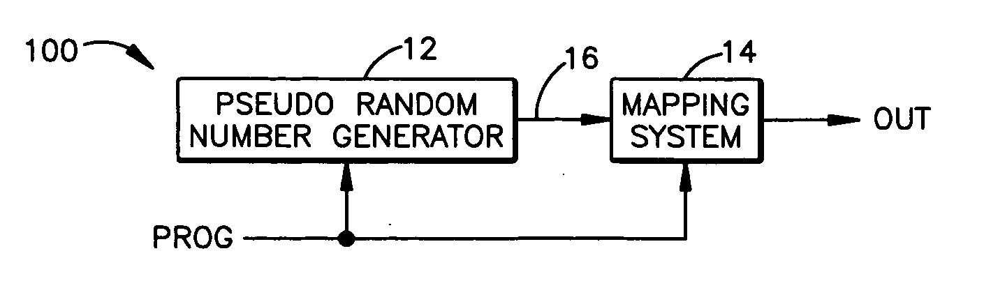
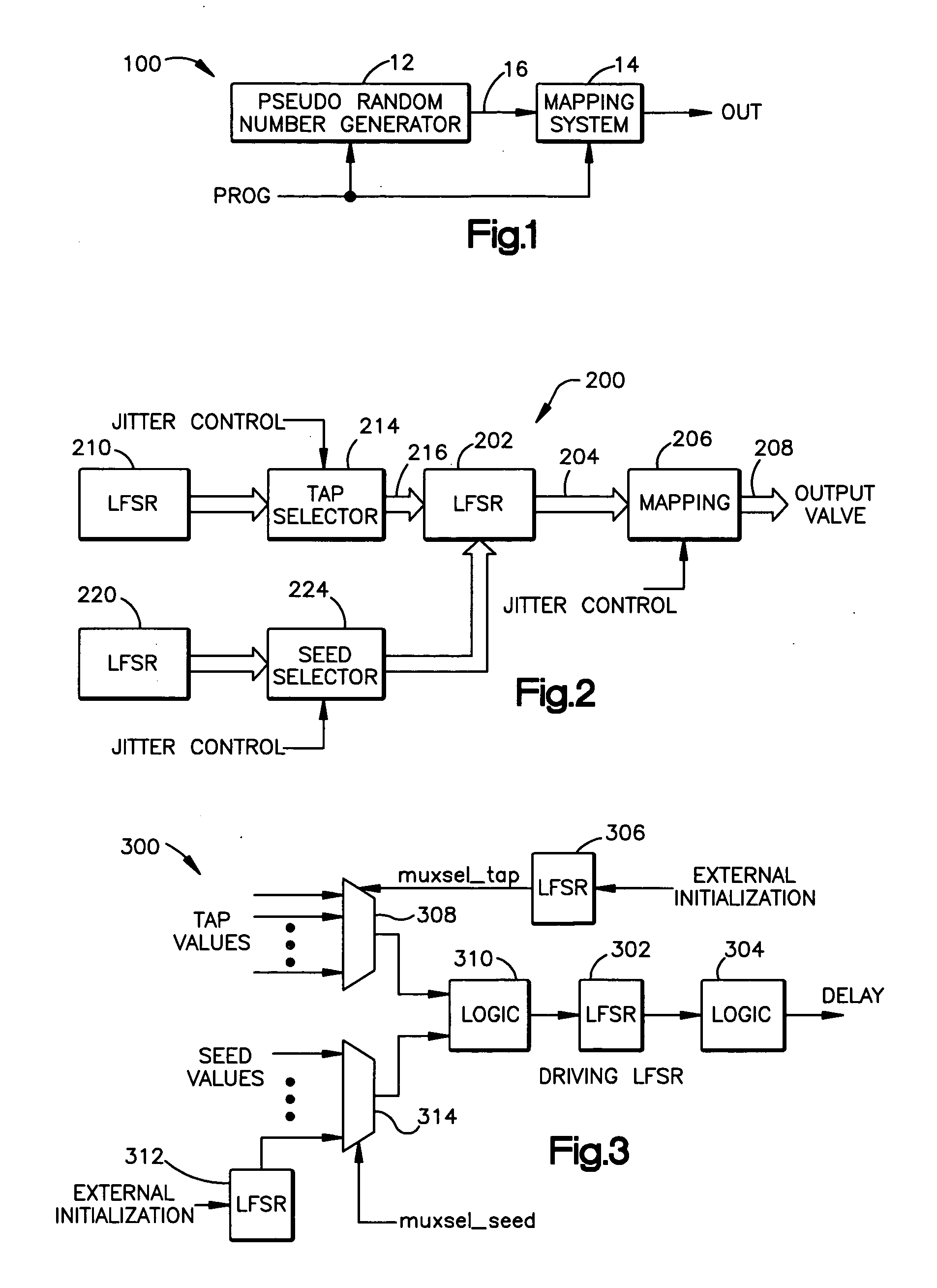
[0021] Referring to FIG. 1, there is illustrated a system 100 in accordance with an aspect of the present invention. The system 100 comprises a pseudorandom number generator 12 that produces a pseudorandom number that is sent along path 16 to a mapping sy...


PUM


Abstract

A system that has a pseudorandom number generator and a mapping system. The pseudorandom number generator generates a random number that is mapped by the mapping system to an output value that is selected from a set of predetermined output values. To increase the randomness of the sequence of numbers generated by the pseudorandom number generator, a tap and / or seed value of the pseudorandom number generator can be varied.

Description

TECHNICAL FIELD [0001] The present invention is directed to the generation of pseudorandom numbers. BACKGROUND OF THE INVENTION [0002] Pseudorandom numbers have many applications in communications, testing, and radar systems. Pseudorandom numbers are usually generated as a sequence of numbers. When generating pseudorandom numbers, it is desirable that each pseudorandom number is maximal (random and doesn't repeat often) and uniform, (each number in the sequence occurs with the same probability). [0003] A linear feedback shift register (LFSR) can be used for generating pseudorandom number sequences. The typical LFSR is a serial shift register that uses feedback taps, such as exclusive-or gates, at one or more of the memory cells to generate the pseudorandom states. If the LFSR is initialized in a non-zero state, it cycles through a sequence of states and eventually returns to its initial state. The sequence can be varied by changing the feedback taps, or by using a different seed val...

Claims


Application Information

Patent Timeline
Patent Type & Authority Applications(United States)
IPC IPC(8): G06F7/58H04L9/00
CPCG06F7/584
Inventor PITZ, JEANNE KRAYERTEUTSCH, ALEXANDERCUNNINGHAM, NICOLE
Owner TEXAS INSTR INC
Why Eureka
Try Eureka