Method, display apparatus and burn-in reduction device for reducing burn-in on display device

a display device and burn-in reduction technology, which is applied in the field of display apparatus and burn-in reduction devices, can solve the problems of failure to change the luminance of images, the display device described above fails to provide sufficient effect on burn-in reduction on the screen, etc., and achieves the effect of reducing burn-in, and reducing burn-in on the screen

Inactive Publication Date: 2005-09-29
PIONEER CORP
View PDF7 Cites 61 Cited by
  • Summary
  • Abstract
  • Description
  • Claims
  • Application Information

AI Technical Summary

Benefits of technology

[0066] Moreover, according to the present invention, the method of reducing burn-in on a screen in a display device comprises the steps of detecting a statistical distribution with respect to luminance levels of pixels of an image based on an input image signal, and changing a luminance level of the input image signal in accordance with the statistical distribution, so that the burn-in can be reduced in a more favorable manner than before.
[0067] Additionally, according to the present invention, the burn-in reduction device may further comprise image dividing means for dividing an image to be displayed of the input image signal into a plurality of blocks; image combining means for combining the plurality of blocks obtained by the image dividing means; nonlinear processing means for performing nonlinear processing on at least one of the blocks obtained by the image dividing means, before the combination of the blocks by the image combining means; and operation mode selecting means for selecting either a first operation mode or a second operation mode, the first operation mode being a mode in which an image signal having the luminance level changed by the luminance changing means is supplied for display, and the second operation mode being a mode in which an image signal on which image processing is performed by the image dividing means, the image combining means and the nonlinear processing means is supplied for display. In this burn-in reduction device, for example, when a portion of an image to be displayed of an input image signal is likely to cause screen burn-in, the screen burn-in can be reduced by applying nonlinear processing only to the portion of the image such that a light / dark difference of the image is reduced, whereas the remaining part of the image can be displayed with normal brightness by applying nonlinear processing for displaying with normal brightness or not applying nonlinear processing. Also, when a part of a display screen displays an image so as to highlight a white color and the remaining part of the display screen displays a dark image, the dark image can be seen clearly by applying nonlinear processing to the dark image so as to increase the number of grayscale levels and thereby improve the image quality.

Problems solved by technology

However, the prior art display device described above fails to provide sufficient effect on the burn-in reduction on the screen because the prior art detects an average luminance over the screen by detecting APL.
Specifically, the prior art display device cannot determine, for example, whether or not an image includes a large number of pixels at a white level, and cannot therefore detect whether or not an image predominantly includes pixels at a black level substantially over the screen while including a few number of pixels at a white level, thus failing to change the luminance of the image.

Method used


Image

  • Method, display apparatus and burn-in reduction device for reducing burn-in on display device
  • Method, display apparatus and burn-in reduction device for reducing burn-in on display device
  • Method, display apparatus and burn-in reduction device for reducing burn-in on display device

Examples


first embodiment

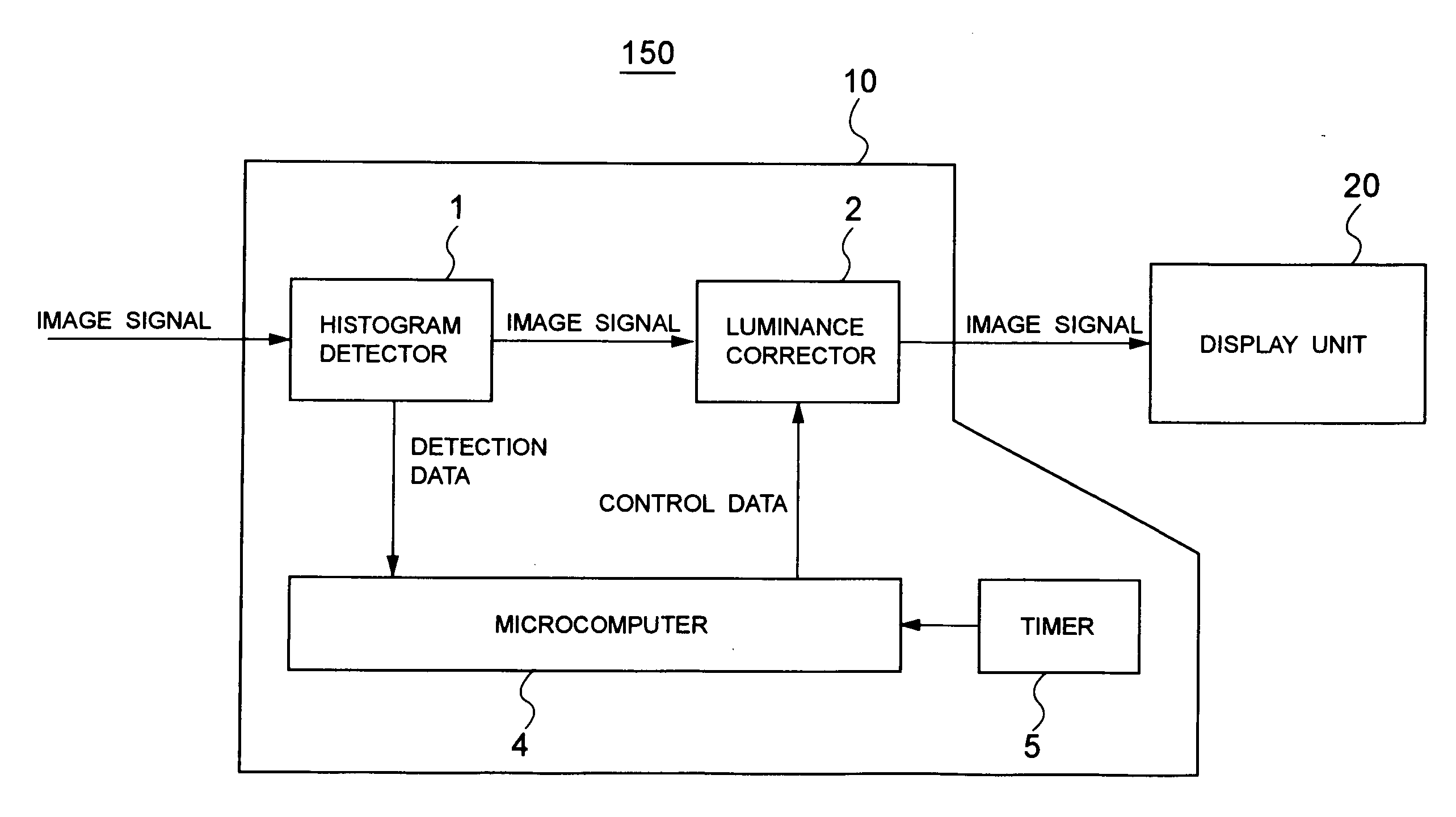
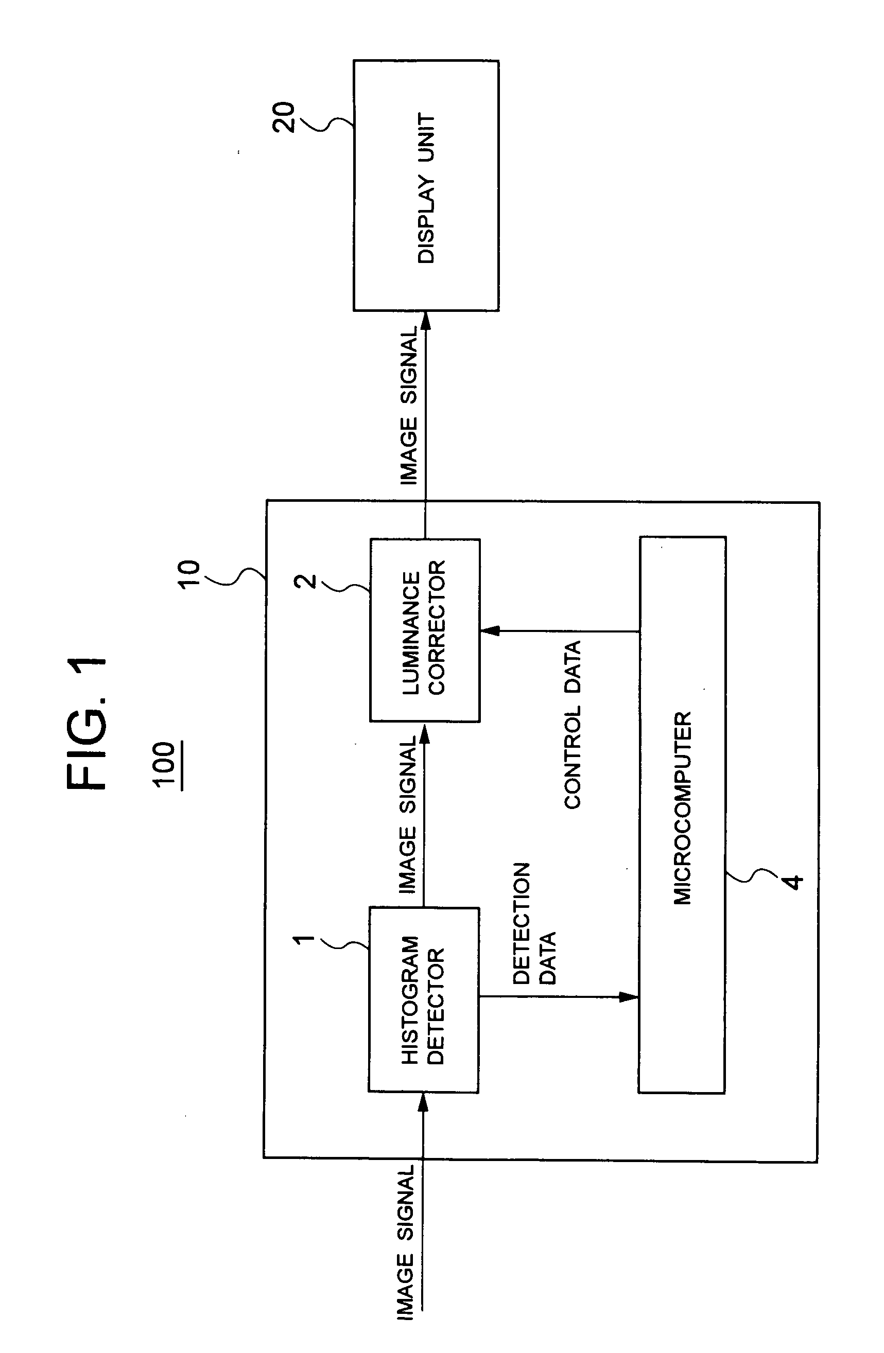
[0096]FIG. 1 is a block diagram illustrating a configuration of a display device 100 which is a first embodiment.

[0097] As illustrated in FIG. 1, the display device 100 according to the first embodiment comprises a burn-in reduction unit (burn-in reduction device) 10 for reducing burn-in on a display screen by luminance correction processing on an input image signal; and a display unit 20 for receiving the image signal corrected or not corrected by a luminance corrector 2 (to be described later) of the burn-in reduction unit 10 and for displaying an image based on the received image signal.

[0098] Among these, the burn-in reduction unit 10 comprises a histogram detector (luminance level distribution detecting means) 1 for detecting a statistical distribution as a histogram representation with respect to luminance levels of pixels included in an image based on the input image signal; a luminance corrector 2 for receiving an image signal through the histogram detector 1 to change or ...

second embodiment

[0176] While the foregoing first embodiment has been described for an example in which a luminance level distribution is detected over the entire display screen to correct the luminance level, a second embodiment will be described for an example in which a luminance level distribution is detected in a partial display area of one display screen to correct the luminance level in this display area.

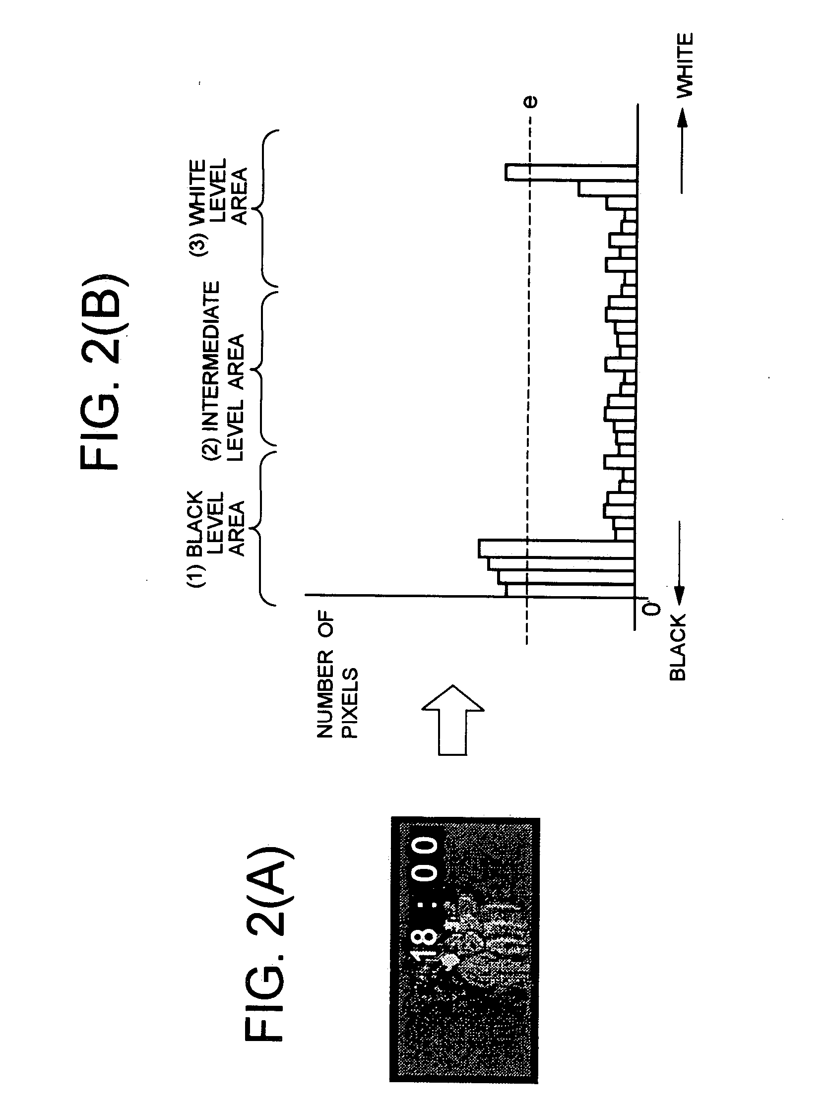
[0177]FIG. 12 and FIG. 13 include diagrams illustrating operations of the second embodiment, wherein FIG. 12(A) illustrates an example of an image displayed on a screen, and FIG. 12(B) illustrates a luminance level distribution as a histogram representation when the image of FIG. 12(A) is displayed. Also, FIG. 13(A) illustrates another example of an image displayed on a screen, and FIG. 13(B) illustrates a luminance level distribution as a histogram representation when the image of FIG. 13(A) is displayed.

[0178] Also in the second embodiment, the configuration of the display device 100 is s...

third embodiment

[0186]FIG. 14 is a block diagram illustrating the configuration of a display device 300 which is a third embodiment of the present invention.

[0187] While each of the foregoing embodiments has been described for an example in which the display device comprises only one histogram detector 1, the third embodiment will be described for the display device which comprises a plurality of histogram detectors 1, 1A, as illustrated in FIG. 14.

[0188] Since the display device 300 of the third embodiment is different from the display device 100 of the foregoing first embodiment only in the following respects, but is configured similarly to the display device 100 of the first embodiment in other respects, the components in the display device 300 of the third embodiment similar to those in the display device 100 have the same reference numerals and the descriptions thereof are omitted.

[0189] Specifically, in the third embodiment, a previous histogram detector (first luminance level distribution...


PUM


Abstract

Disclosed is a burn-in reduction device capable of favorably reducing burn-in on a screen. The burn-in reduction device comprises luminance level distribution detecting means for detecting a statistical distribution with respect to luminance levels of pixels of an image based on an input image signal; and luminance changing means for changing a luminance level of the input image signal in accordance with the statistical distribution detected by the luminance level distribution detecting means.

Description

BACKGROUND OF THE INVENTION [0001] 1. Field of the Invention [0002] The present invention relates to a display apparatus and a burn-in reduction device for reducing burn-in on a display device, and to a method and a program for reducing burn-in on a display device. [0003] 2. Description of the Related Art [0004] When the display device presents, for example, high luminance pixels at a white level locally displayed on the screen thereof and pixels at a black level surrounding the white pixels for a long time period, image burn-in will occur on the screen. [0005] A conventional technique for reducing such burn-in on the screen is described in, for example, Japanese Patent Kokai No. 2000-305514. [0006] Japanese Patent Kokai No. 2000-305514 discloses a display device comprising an APL detector 101 for detecting APL (Average Picture Level) of an image signal; a luminance controller for controlling (or changing) the luminance in accordance with a detection signal from the APL detector 101...

Claims


Application Information

Patent Timeline
Patent Type & Authority Applications(United States)
IPC IPC(8): G06K9/00G09G3/22G09G3/28
CPCG09G3/22G09G3/28G09G2320/0271G09G2320/046G09G2320/066G09G2320/0666G09G2320/0673G09G2360/16
Inventor NAMBA, KIYOSHIYOSHIDA, TAKUMA
Owner PIONEER CORP
Why Eureka
Try Eureka