Eureka AIR delivers breakthrough ideas for toughest innovation challenges, trusted by R&D personnel around the world.

Graphic object designating apparatus, graphic object designating method, and graphic object designating program

a technology of object design and object design, which is applied in the field of graphic object designating apparatus, graphic object designating method and graphic object designating program, can solve the problems of difficult object designation, difficult object designation for operators, so as to reduce the display size of objects, and accurately designate a desired object

Inactive Publication Date: 2005-09-29
FUJITSU LTD
View PDF7 Cites 7 Cited by
  • Summary
  • Abstract
  • Description
  • Claims
  • Application Information

AI Technical Summary

Benefits of technology

[0013] Accordingly, an object of the present invention is to provide a graphic object designating apparatus, a graphic object designating method and a graphic object designating program that allow the operator to designate a desired object easily within the object display screen.
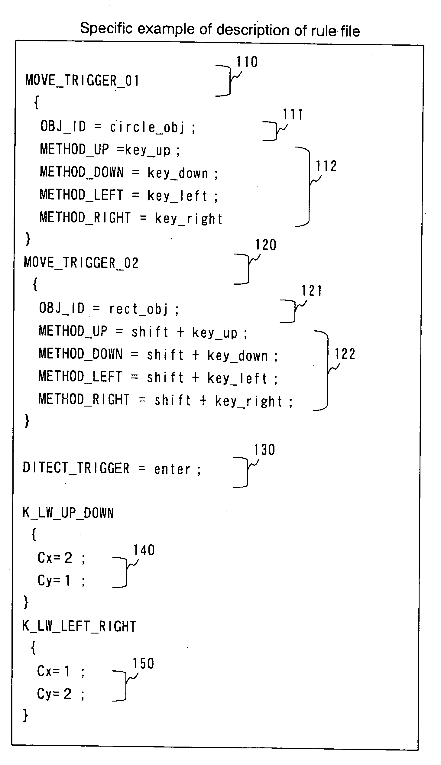
[0024] According to the present invention, even when an object displayed on the display screen is small in size or a large number of objects are present in the display screen at a high density, the operator can accurately designate a desired object by a key-in operation. Even when various types of objects are present in the display screen, the operator can accurately designate a desired object by restricting the type of objects to which the mouse cursor is movable through a key-in operation. Even when performing a graphics editing operation on a device where the mouse cursor is difficult to move accurately, such as a touch pad of a notebook-model personal computer, the operator can designate a desired object accurately because the editing can be performed by a key-in operation. In addition, because types of triggers and methods of generating triggers are described in the form of a rule file, various types of objects can be designated.
[0025] Further, because the operator can designate a desired object accurately, the display size of objects can be reduced. Consequently, the amount of information that can be obtained from one screen can be increased to a considerable extent without degrading the operability. In addition, because the operator can designate a desired object accurately, the efficiency of the graphics editing operation increases, and hence the time required for the operation can be reduced.

Problems solved by technology

However, the object designating method using the mouse cursor involves the following problems.
First, when objects displayed on the display screen are small in size, it is difficult for the operator to designate them.
When performing an operation in an environment where the mouse cursor is difficult to move freely, it is difficult for the operator to designate objects.
For example, when objects are designated by moving the mouse cursor using a touch pad on a notebook-model personal computer, it is difficult to make object designation.
When various types of objects are displayed, it is difficult for the operator to designate desired objects.
For example, when three different types of objects, e.g. rectangular objects, circular objects, and linear objects, are displayed, it is difficult to designate only linear objects.
Therefore, when a very large number of terminals are present, it takes time and labor to move the mouse cursor to a desired terminal.

Method used


Image

  • Graphic object designating apparatus, graphic object designating method, and graphic object designating program
  • Graphic object designating apparatus, graphic object designating method, and graphic object designating program
  • Graphic object designating apparatus, graphic object designating method, and graphic object designating program

Examples


Embodiment Construction

[0050] Embodiments of the present invention will be described below with reference to the accompanying drawings.

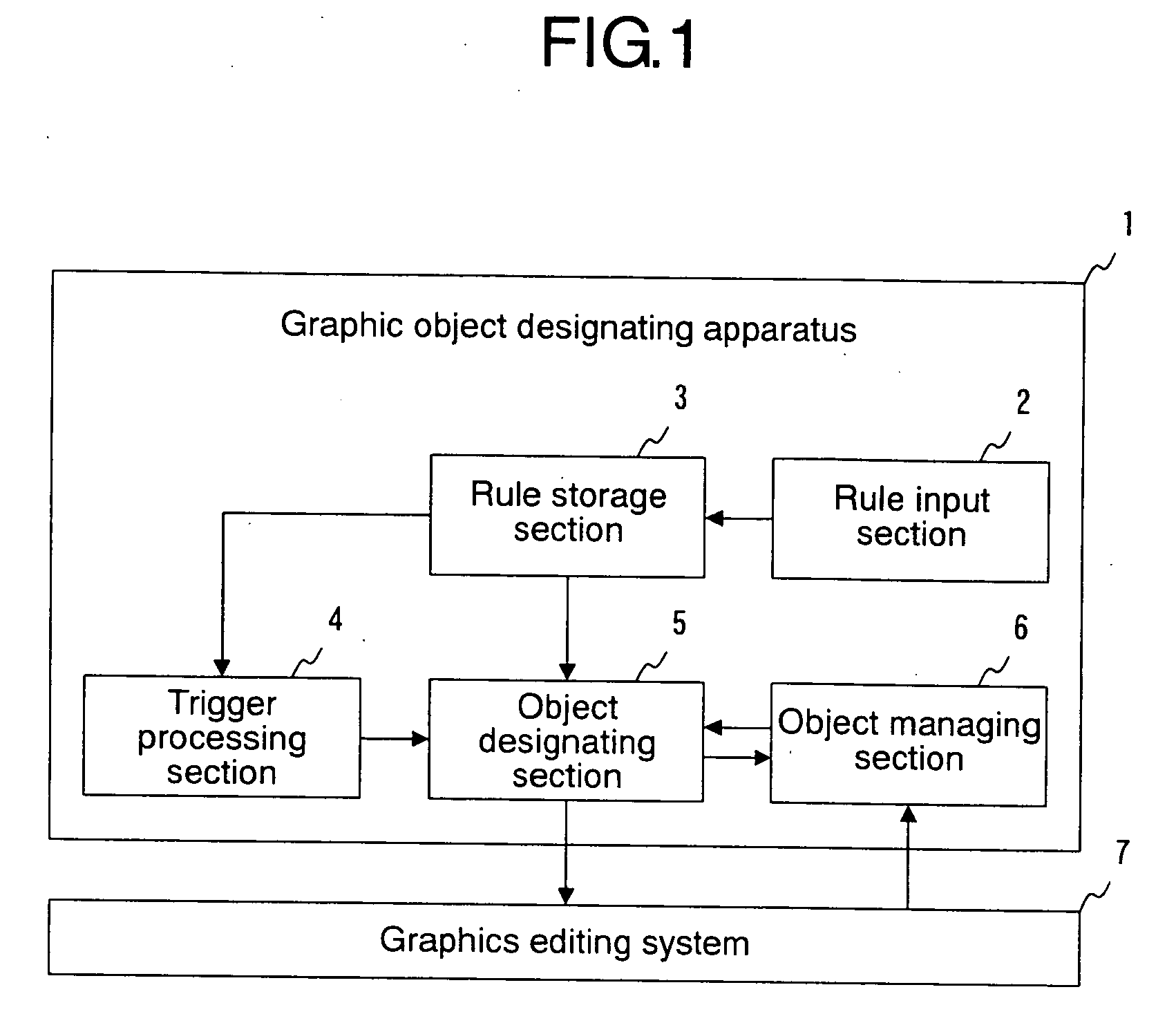
[0051] First, the arrangement of a graphic object designating apparatus according to an embodiment of the present invention will be described. FIG. 1 is a block diagram showing an example of the arrangement of the graphic object designating apparatus according to the embodiment. As shown in FIG. 1, the graphic object designating apparatus 1 includes a rule input section 2, a rule storage section 3, a trigger processing section 4, an object designating section 5, and an object managing section 6. In addition, a graphics editing system 7 that edits graphics by using a GUI is present outside the graphic object designating apparatus 1. In the graphics editing system 7, a part or the whole of an edit area containing objects is displayed as a display screen. When the graphics editing system 7 is a CAD system for designing an LSI logic circuit, for example, the edit area is a su...


PUM


Abstract

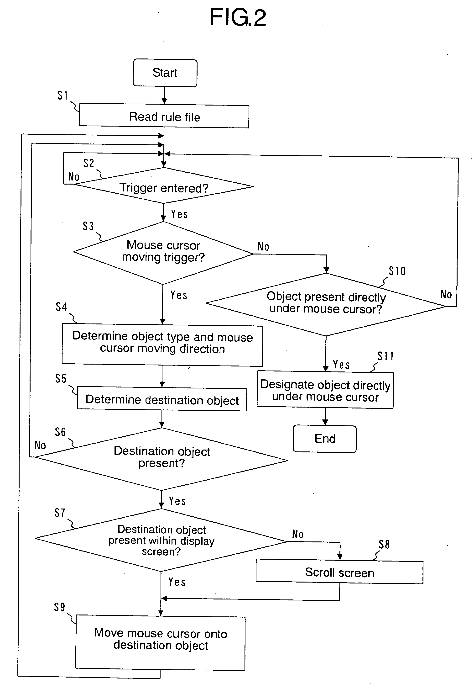
A graphic object designating apparatus for designating a graphic object to be edited among graphic objects present in an edit area of a graphics editing system according to the position of a mouse cursor. The apparatus includes an object managing section that manages object information and the mouse cursor position, and a rule storage section in which assignments of key entries for indicating a direction in which the mouse cursor should move and for designating an object directly under the mouse cursor have previously been stored as rules. A trigger processing section generates a mouse cursor moving trigger or an object designating trigger according to the key entries and the rules. An object designating section moves the mouse cursor or designates the object to be edited on the basis of the object information and the triggers. The apparatus allows an operator to designate a desired object easily within the object display screen.

Description

BACKGROUND OF THE INVENTION [0001] 1. Field of the Invention [0002] The present invention relates to a graphic object designating apparatus, a graphic object designating method and a graphic object designating program for designating graphic objects to be edited on a display screen of a graphics editing system that edits graphic objects by using a GUI (Graphical User Interface). [0003] 2. Description of the Related Art [0004] A conventional graphics editing system and graphic object designating apparatus will be described below. The graphics editing system edits a combination of various types of graphic objects. Objects to be edited are displayed on a display screen of the graphics editing system. For example, rectangular objects and circular objects are displayed on the display screen. When performing some processing on objects, first, the operator of the graphics editing system designates objects to be processed by using a graphic object designating apparatus connected to the grap...

Claims


Application Information

Patent Timeline
Patent Type & Authority Applications(United States)
IPC IPC(8): G06F3/033G06F19/00G06F3/02G06T11/80G09G5/08
CPCG06F3/04892G06F3/04812
Inventor TODA, TAKAHIROAOKI, KATSUSHIMIZUNO, RIMIFURUKAWA, EIJI
Owner FUJITSU LTD
Why Eureka
Eureka Blog
Learn More