Eureka AIR delivers breakthrough ideas for toughest innovation challenges, trusted by R&D personnel around the world.

Image area specification device and method, and X-ray image processing device and method

a technology of image area and specification device, which is applied in the field of image area specification device and method, and x-ray image processing device and method, can solve the problems of difficult to accurately extract the bone part region or the soft part region in the distal portion of the human body, readjust the region, and difficult to allocate an optimal gradation curve. , to achieve the effect of accurately and easily designating preventing another region, and accurately identifying the desired distal portion

Active Publication Date: 2018-09-25
FUJIFILM CORP
View PDF25 Cites 0 Cited by
  • Summary
  • Abstract
  • Description
  • Claims
  • Application Information

AI Technical Summary

Benefits of technology

[0011]The invention has been made in view of the above-mentioned problems and an object of the invention is to provide a technique which can accurately designate a desired distal portion particularly in a radiological image including a distal portion of the human body.
[0023]According to the image region designation device and method of the invention, the partial region including the distal portion in the vicinity of the boundary between the subject region and the void region is extracted, and at least one of the void region and the partial region is determined as the designation region for designating the partial region. Therefore, it is possible to designate the partial region including the distal portion, using the designation region that is wider than the distal portion. As a result, when a desired distal portion is designated, it is possible to prevent another region from being erroneously designated and thus to accurately designate the desired distal portion.
[0024]In the radiological image having a distal portion as a subject, the size of the void region is large. Therefore, when the void region and the partial region, or the void region is determined as the designation region, it is possible to designate the partial region, using the region that is wider than the distal portion. As a result, it is possible to accurately and easily designate a desired distal portion.
[0025]According to the radiological image processing device and method of the invention, when the designation region is designated, a feature amount which is concentration of the radiological image is calculated on the basis of the partial region including the distal portion, the target concentration which is converted from the feature amount is calculated, and image processing including a gradation process is performed for the radiological image such that the feature amount is the target concentration. Therefore, it is not necessary to set an imaging menu in detail. As a result, it is possible to optimize the quality of the processed radiological image including the distal portion while reducing the number of imaging menus to be set.

Problems solved by technology

However, it is difficult to accurately extract the bone part region or the soft part region in a distal portion of the human body, such as the patella, the nasal bone, a hand, a foot, or a finger.
As a result, it is difficult to allocate an optimal gradation curve and it is necessary to readjust the region.
Therefore, when the soft part region or the bone part region of the distal portion is designated, there is a concern that the void region will be erroneously designated or the bone part will be erroneously designated instead of the intended soft part.
In particular, when a terminal with a small touch panel screen, such as a tablet computer, is used, it is difficult to accurately designate only the desired distal portion.
As such, when it is difficult to accurately designate the desired distal portion, the optimal gradation process is performed for an erroneously designated region.
As a result, the concentration and contrast of the radiological image subjected to the gradation process are not suitable for diagnosis.

Method used


Image

  • Image area specification device and method, and X-ray image processing device and method
  • Image area specification device and method, and X-ray image processing device and method
  • Image area specification device and method, and X-ray image processing device and method

Examples


Embodiment Construction

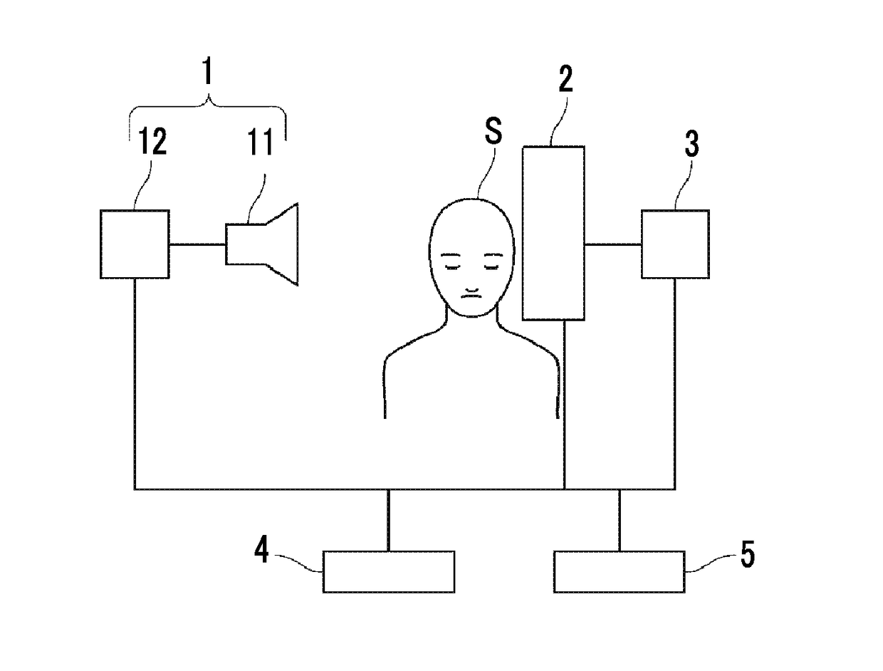
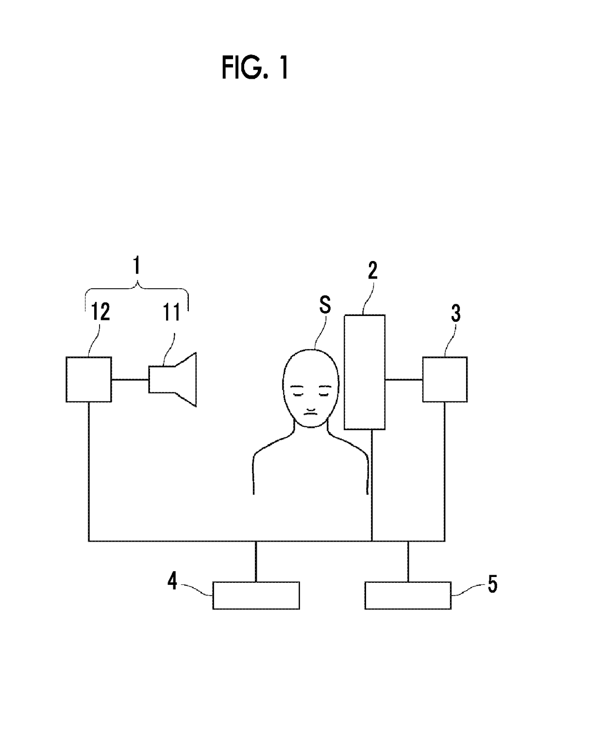
[0040]Hereinafter, embodiments of the invention will be described with reference to the drawings. FIG. 1 is a block diagram schematically illustrating the structure of a radiological image diagnosis system to which an image region designation device and a radiological image processing device according to the invention are applied. As illustrated in FIG. 1, the radiological image diagnosis system includes a radiation generation device 1, a radiation detector 2, a radiological image processing device 3, an imaging control device 4, and an input unit 5. The radiation generation device 1 and the radiation detector 2 are arranged so as to face each other, with a subject S interposed therebetween. The image region designation device is provided in the radiological image processing device 3. The imaging control device 4 is connected to the radiation generation device 1, the radiation detector 2, the radiological image processing device 3, and the input unit 5, and the radiation detector 2 ...


PUM


Abstract

A partial region extraction unit extracts a partial region including a distal portion in the vicinity of a boundary between a subject region including the distal portion and a void region from a radiological image including the distal portion of the human body. A designation region determination unit determines at least one of the void region and the partial region as a designation region for designating the partial region.

Description

CROSS REFERENCE TO RELATED APPLICATIONS[0001]The present application is a Continuation of PCT International Application No. PCT / JP2014 / 004313 filed on Aug. 21, 2014, which claims priority under 35 U.S.C. § 119(a) to Japanese Patent Application No. 2013-175219 filed on Aug. 27, 2013. Each of the above applications is hereby expressly incorporated by reference, in its entirety, into the present application.BACKGROUND OF THE INVENTION[0002]1. Field of the Invention[0003]The present invention relates to an image region designation device and method which designates a necessary region in a radiological image and a radiological image processing device and method which performs a gradation process for a radiological image.[0004]2. Description of the Related Art[0005]A radiological image used in an image diagnosis is acquired by an imaging process of a computed radiography (CR) system or an imaging process using a radiation detector (FPD). The dynamic range of the acquired radiological imag...

Claims


Application Information

Patent Timeline
Patent Type & Authority Patents(United States)
IPC IPC(8): G06K9/00G06T5/00G06T5/40G06T7/00A61B6/00G06K9/46
CPCG06T7/0012A61B6/505A61B6/5211G06K9/4604G06T5/40G06T5/009G06T2207/30008G06T2207/10116G06T2207/20008G16H50/20
Inventor NAKAMURA, KEIGOTAKAHASHI, TOMOYUKI
Owner FUJIFILM CORP
Why Eureka
Eureka Blog
Learn More