Eureka AIR delivers breakthrough ideas for toughest innovation challenges, trusted by R&D personnel around the world.

Liquid ejecting head and liquid ejecting apparatus

a liquid ejector and liquid ejector technology, applied in printing and other directions, can solve the problems of insufficient compliance section function, likely to be restored the adhesive power of the adhesive, and problems not only in the ink jet recording head but also in the ink jet recording head

Active Publication Date: 2016-08-11
SEIKO EPSON CORP
View PDF0 Cites 0 Cited by
  • Summary
  • Abstract
  • Description
  • Claims
  • Application Information

AI Technical Summary

Benefits of technology

[0009]An advantage of some aspects of the invention is to provide a liquid ejecting head and a liquid ejecting apparatus in which it is possible to prevent a compliance region from adhering to a cap member such that it is possible to reduce malfunction of the compliance region due to the adherence.Aspect 1
[0011]In this case, the island-like member is provided, and thereby it is possible to prevent the compliance region of the flexible member from coming into contact with and adhering to the cap member and to prevent the compliance region of the flexible member from malfunctioning by adhering to the cap member. In addition, the island-like member is not fixed to one of the flexible member and the cap member, and thereby it is possible for the compliance region to be significantly deformed in deflection toward the inner side of the manifold and it is possible for the compliance region to reliably perform pressure absorption in the manifold. Further, the island-like member is thinner in the thickness than the frame-like member, and thereby it is possible to prevent the compliance region from having a reduced amount of deformation to the cap member side.Aspect 2
[0012]In the liquid ejecting head according to Aspect 1, it is preferable that, in a case where it is assumed that the compliance region is defined in a longitudinal direction and a widthwise direction, the island-like member is disposed to be shifted from the center of the compliance region in the widthwise direction. In this case, it is possible to prevent the deformation of the center position of the compliance region, which has the maximum deformation amount, from being restraint by the island-like member and to prevent the deformation amount of the compliance region from being reduced.Aspect 3
[0024]In this case, it is possible to realize the liquid ejecting apparatus in which the compliance region is prevented from adhering and malfunction due to the adhesion of the compliance region is reduced.

Problems solved by technology

However, a problem arises in that the film is likely to be deflected during manufacture such as a process in which the films used to form the compliance section adhere, the deflected film is to likely to adhere to another member (cap member) that demarcates a space between the compliance section and the film due to condensation or the like, and the compliance section does not appropriately function.
Particularly, since the film is joined using an adhesive, another problem arises in that adhesive power of the adhesive is likely to be restored due to high-temperature and high-humidity surroundings and the film is likely to adhere to the other member (cap member) with the adhesive.
Further, such problems arise not only in the ink jet-type recording head but also similarly in a liquid ejecting apparatus that ejects a liquid except for the ink.

Method used


Image

  • Liquid ejecting head and liquid ejecting apparatus
  • Liquid ejecting head and liquid ejecting apparatus
  • Liquid ejecting head and liquid ejecting apparatus

Examples


embodiment 1

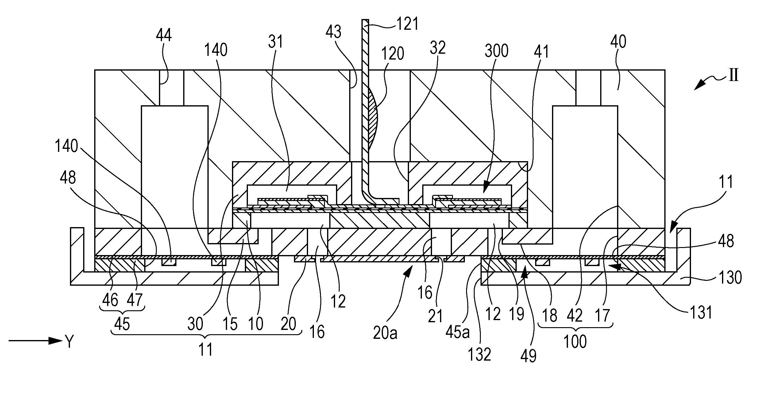
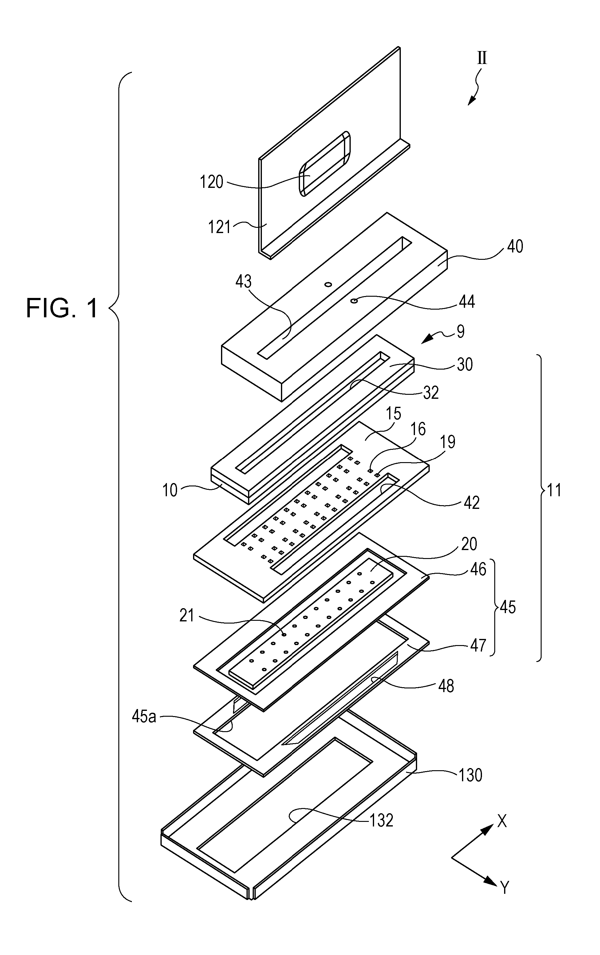
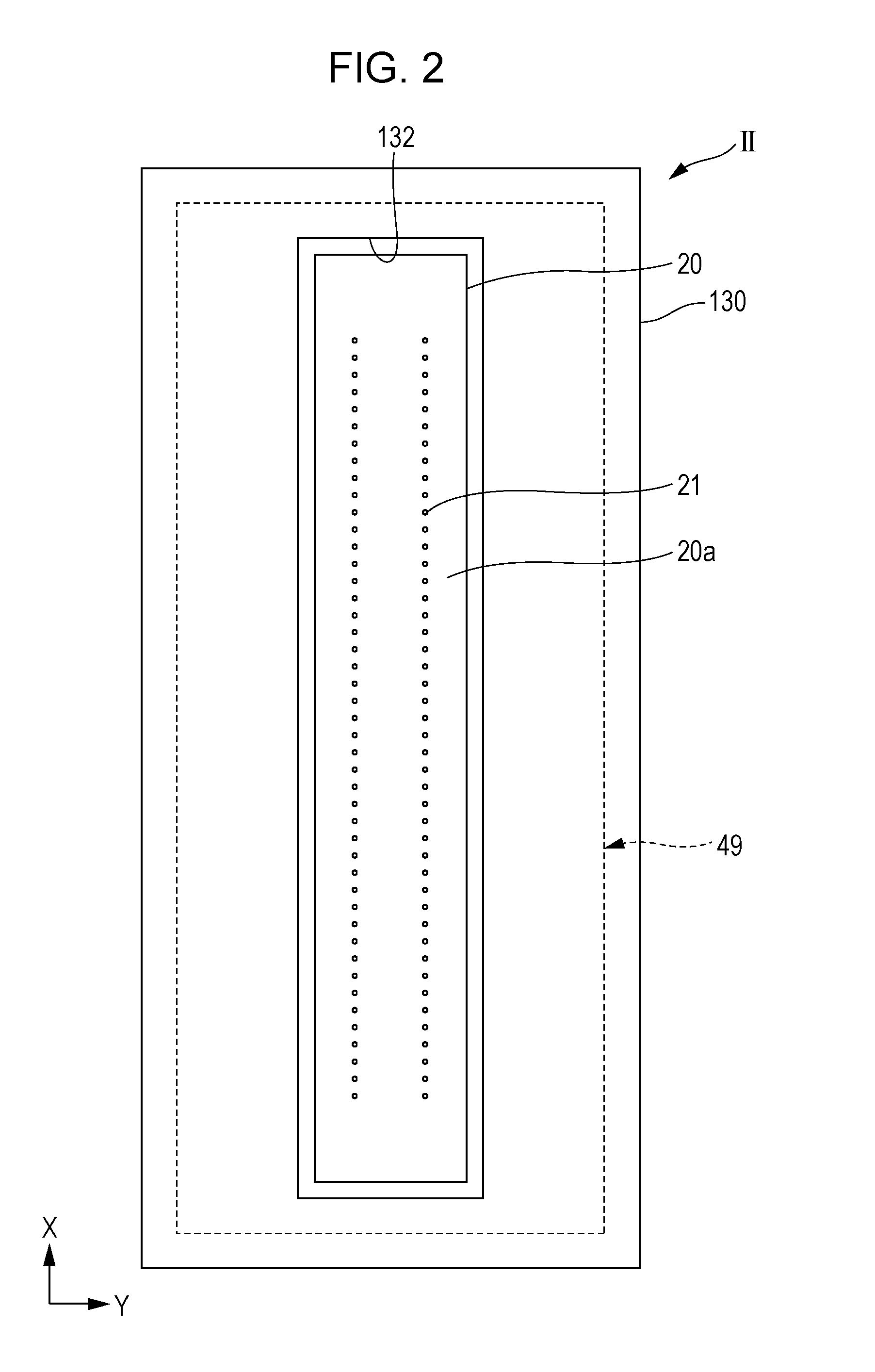
[0047]FIG. 1 is an exploded perspective view illustrating an ink jet-type recording head as an example of a liquid ejecting head according to Embodiment 1 of the invention. FIG. 2 is a plan view illustrating the ink jet-type recording head. In addition, FIG. 3 is a plan view illustrating a compliance substrate and FIG. 4 is a sectional view illustrating the recording head taken along line IV-IV in FIG. 3. FIG. 5 is an enlarged sectional view illustrating main components in FIG. 4.

[0048]As illustrated in the FIG. 1 to FIG. 4, the ink jet-type recording head II (hereinafter, also simply referred to as a recording head II) includes a plurality of members such as a head main body 11, a case member 40 fixed to one surface side of the head main body 11, a cover head 130 fixed to the other surface side of the head main body 11. In addition, the head main body 11 of Embodiment 1 includes a flow path formation substrate 10, a communicating plate 15 provided on one surface side of the flow pa...

embodiment 2

[0097]FIG. 14 is a plan view of a compliance substrate of an ink jet-type recording head according to Embodiment 2 of the invention. FIG. 15 is a sectional view taken along line XV-XV in FIG. 14. FIG. 16 is an enlarged sectional view of main components in FIG. 15.

[0098]As illustrated in the drawings, the same island-like member 140 as in Embodiment 1 described above, and a cantilever 150 are provided in the compliance space 131 between the compliance region 49 and the cover head 130.

[0099]The cantilever 150 is provided in the compliance space 131 between the flexible member 46 and the cover head 130 and is provided to be continued from the frame-like member 47 in the second direction Y and to protrude in the compliance space 131. Further, in Embodiment 2, an end side of the cantilever 150, which is continuous to the frame-like member 47, is referred to as a support point side and the end side protruding into the compliance space 131 is referred to as a distal end side. In Embodiment...


PUM


Abstract

A liquid ejecting head includes generating chambers communicating with nozzles, a manifold communicating with the pressure generating chambers, a flexible member that has a compliance region, which is able to perform deflection in response to pressure fluctuation in the manifold, a compliance space disposed on a side opposite to the manifold through the flexible member, a cap member facing the flexible member through the compliance space; a frame-like member disposed between the flexible member and the cap member, and an island-like member to be disposed in the compliance region and separated from the frame-like member. One surface of the frame-like member faces the flexible member and the other surface faces the cap member. In a direction in which the flexible member and the cap member face each other, the island-like member is thinner in thickness than the frame-like member.

Description

BACKGROUND[0001]1. Technical Field[0002]The present invention relates to a liquid ejecting head that ejects a liquid from a nozzle and a liquid ejecting apparatus, and particularly to an ink jet-type recording head that ejects ink as the liquid and an ink jet-type recording apparatus.[0003]2. Related Art[0004]As an ink jet-type recording head which is a representative example of a liquid ejecting head that ejects a droplet, there is a recording head which includes a nozzle and a flow path such as a pressure generating chamber communicating with the nozzle, and in which a pressure generator causes pressure in ink in the pressure generating chamber to be changed such that an ink droplet is discharged from the nozzle.[0005]According to the ink jet-type recording head, there has been proposed a recording head in which a so-called compliance section that is formed by a flexible film demarcating a part of a manifold, with which a plurality of pressure generating chambers communicate, and ...

Claims


Application Information

Patent Timeline
Patent Type & Authority Applications(United States)
IPC IPC(8): B41J2/165
CPCB41J2/16505B41J2/055B41J2/14233B41J2002/14419
Inventor KANEGAE, TAKAHIROOKUBO, KATSUHIROOWAKI, HIROSHIGEKATO, TAKASHI
Owner SEIKO EPSON CORP
Why Eureka
Eureka Blog
Learn More