Pressure activated fingerprint input apparatus

Inactive Publication Date: 2005-09-29
CASIO COMPUTER CO LTD
View PDF8 Cites 50 Cited by
  • Summary
  • Abstract
  • Description
  • Claims
  • Application Information

AI Technical Summary

Benefits of technology

[0009] It is an object of the present invention to provide an image input apparatus

Problems solved by technology

Also, when a finger is an object to be examined, it is conventionally impossible to sense th

Method used


Image

  • Pressure activated fingerprint input apparatus
  • Pressure activated fingerprint input apparatus
  • Pressure activated fingerprint input apparatus

Examples


first embodiment

[First Embodiment]

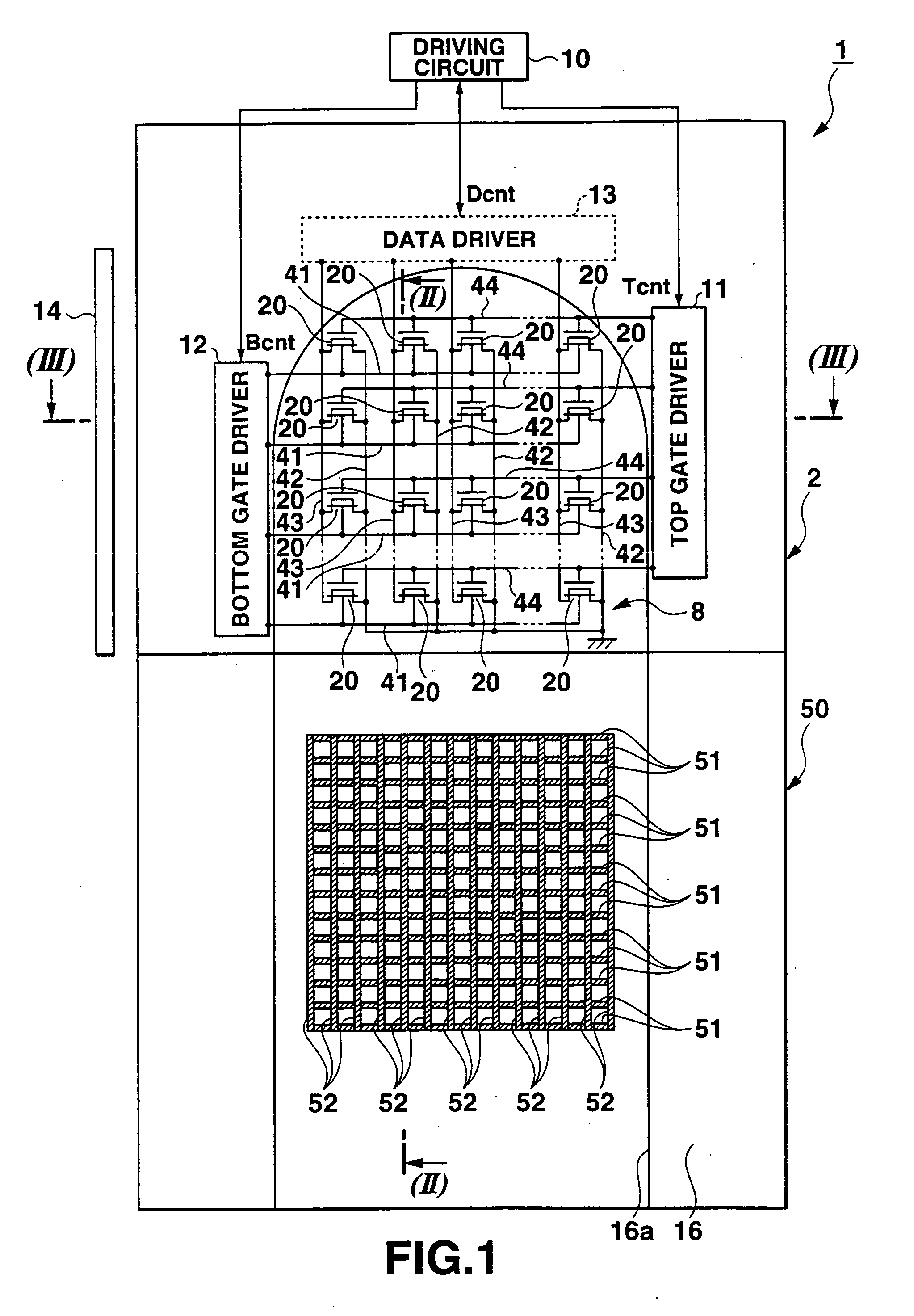
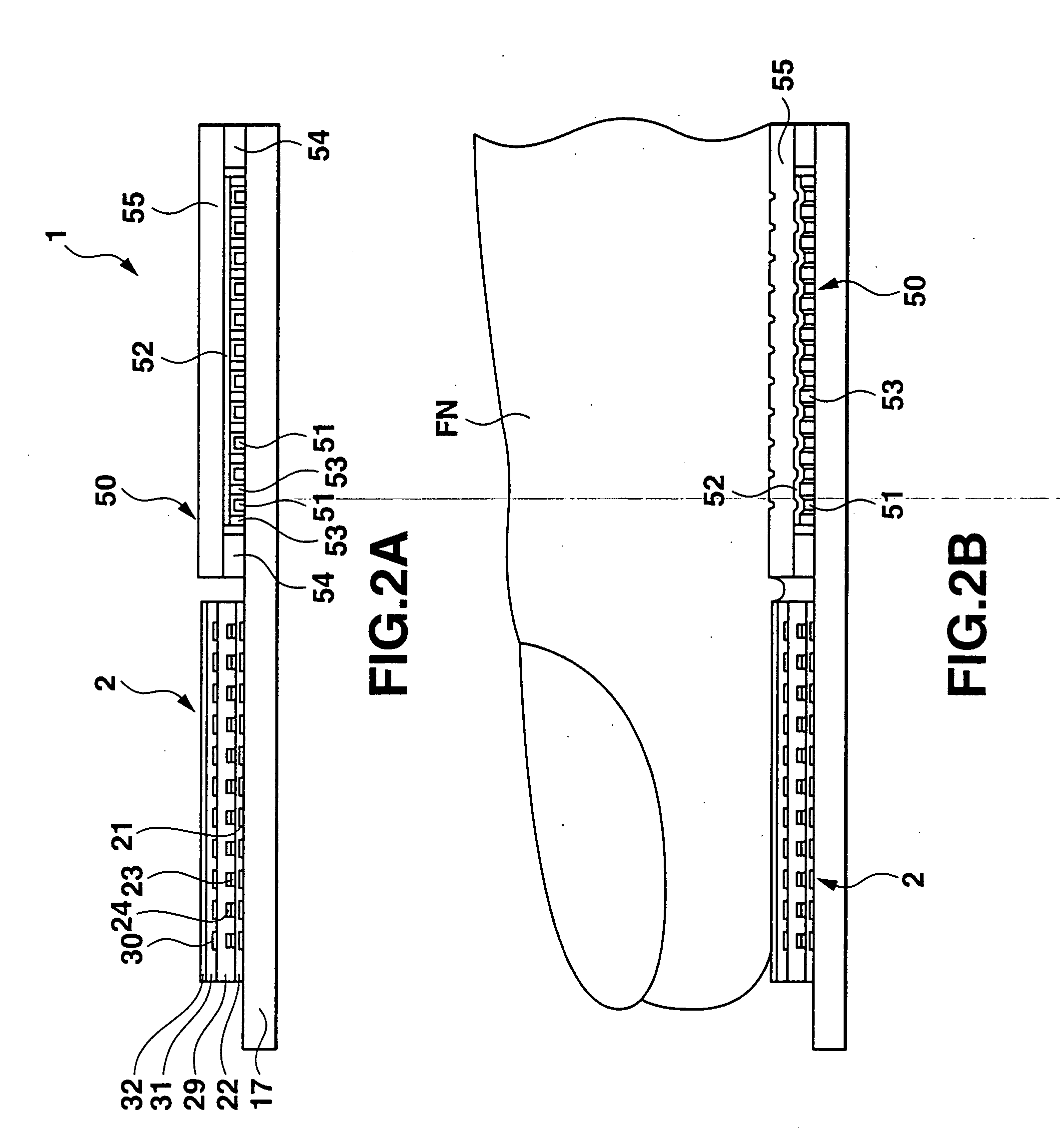
[0031]FIG. 1 is a plan view showing a fingerprint reader 1 to which an image input apparatus of the present invention is applied. FIGS. 2A and 2B are sectional views taken along a line (II)-(II) in FIG. 1 and showing the state in which no finger is placed and the state in which a finger is placed, respectively. FIG. 3 is a sectional view taken along a line (III)-(III) in FIG. 1.

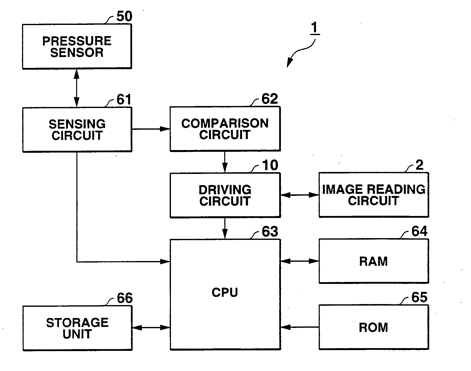
[0032] The fingerprint reader 1 has an image reading circuit 2 or image reading assembly which reads a fingerprint image of a portion of a finger FN beyond the first joint placed on a contact surface 32a, by converting the amount or intensity of light reflected by the finger FN and that of light transmitted through the finger FN into electrical signals. The image reading circuit 2 is obtained by integrating a solid-state image pickup device and its drivers, and includes the contact surface 32a on one side, in this embodiment, the upper side. The fingerprint reader 1 also comprises a driving...

second embodiment

[Second Embodiment]

[0089] A fingerprint reader 101 different from the fingerprint reader 1 of the first embodiment will be described below with reference to FIGS. 6A to 8.

[0090] In the second embodiment, a diffusion light-guiding plate 15 overlaps an image reading circuit 2, and that surface of the diffusion light-guiding plate 15, which faces the rear surface of the image reading circuit 2 is in contact with the rear surface of the image reading circuit 2.

[0091] In the above first embodiment, the surface of the pressure sensor 50 is on the same level as the contact surface 32a of the image reading circuit 2. In the second embodiment, however, a pressure sensor 50 overlaps the diffusion light-guiding plate 15, and the surface of the pressure sensor 50 is in contact with the rear surface of the diffusion light-guiding plate 15. That is, the fingerprint reader 101 is obtained by stacking the pressure sensor 50, diffusion light-guiding plate 15, and image reading circuit 2 in this or...


PUM


Abstract

An image input apparatus includes an image reading assembly positioned below a placement surface on which an object to be examined is placed, and a sensing circuit for sensing that the object is placed on the placement surface, in accordance with a pressure applied to the placement surface.

Description

CROSS REFERENCE TO RELATED APPLICATIONS [0001] This is a Continuation Application of PCT Application No. PCT / JP03 / 15845, filed Dec. 11, 2003, which was published under PCT Article 21(2) in Japanese. [0002] This application is based upon and claims the benefit of priority from prior Japanese Patent Application No. 2002-368558, filed Dec. 19, 2002, the entire contents of which are incorporated herein by reference. BACKGROUND OF THE INVENTION [0003] 1. Field of the Invention [0004] The present invention relates to an image input apparatus which includes an image reading circuit positioned below a placement surface on which an object to be examined is placed, and inputs an image of the object by reading the object by an image reading device. [0005] 2. Description of the Related Art [0006] A fingerprint has a pattern unique to an individual and hence is a very useful means for authenticating a person. Recently, a fingerprint authentication apparatus which applies a fingerprint to persona...

Claims


Application Information

Patent Timeline
IPC IPC(8): G06K9/00
CPCG06K9/0002G06V40/1306
Inventor SAWANO, TOMOMI
Owner CASIO COMPUTER CO LTD
Why Eureka
Try Eureka