Document reader

a document reader and document technology, applied in the field of document readers, can solve the problems of high possibility of document jam, high time required for reading the images formed on both sides, and restricting the installation space or durability against vibration, and achieve the effect of easy maintenan

Inactive Publication Date: 2010-02-23
SHARP KK
View PDF11 Cites 6 Cited by
  • Summary
  • Abstract
  • Description
  • Claims
  • Application Information

AI Technical Summary

Benefits of technology

[0023]The present invention has been accomplished in view of the above-described circumstances in the conventional art. Therefore, an object of the present invention is to provide a document reader capable of clearly reading images formed on first and second sides, which requires a short period of time from image reading to image outputting and in which maintenance is readily conducted.
[0025]According to the present invention, each of the first and second image reading means is of the optical reduction system constituted of the light source, the mirror, the lens and the image sensor, and therefore, the read images on the first and second sides become clear with an excellent resolution. In addition, image processing for achieving the same image quality of the data on the images on the first and second sides can be simplified or omitted, so that a burden on a controller can be relieved, and further, a time from image reading to image outputting can be shortened.
[0026]Moreover, the second image reading means is unified into the assembly, to be thus detachably attached to the document feeding means as the single unit. Therefore, when the maintenance is conducted, the second image reading means is detached from the document feeding means, and then, the maintenance can be conducted, thereby saving the energy for the maintenance and shortening the maintenance time.

Problems solved by technology

Therefore, much time has been required for reading the images formed on both sides.
In addition, the use of the switch-back path complicates a document conveyance control and, further, causes the high possibility of a document jam.
However, the second image reading means has been disposed on the way of the document conveyance path in the ADF repeatedly opened or closed at frequent intervals with respect to the platen; therefore, there has been a restriction from the viewpoint of an installation space or durability against vibration.
In deed, the image sensor of the contact type is superior to the image reading means of the optical reduction system from the viewpoint of the installation space or the durability against the vibration, but is inferior to the image reading means of the optical reduction system from the viewpoint of a resolution or a focal depth.
Consequently, the image formed on the first side read by the image reading means of the optical reduction system is clear; however, the image formed on the second side read by the image sensor of the contact type is liable to become more unclear than the read image formed on the first side.
However, such image processing imposes a heavy burden on a controller in the document reader and, hinders in shortening a time after image reading till image outputting.
Therefore, if the image reading means of the optical reduction system is disposed on the way of the document conveyance path in the ADF, there is induced a fear that an optical axis cannot be constantly kept caused by the deviation of an inclination angle of a mirror due to the repeated vibrations.
However, if the image reading means of the optical reduction system is merely disposed on the way of the document conveyance path in the ADF, there may occur an inconvenience that the maintenance of the image reading means of the optical reduction system cannot be conducted unless the ADF is disassembled every maintenance.
This not only requires much labor and skill for a maintenance service person but also forces a user to suffer an inconvenience of a long waiting time after the start of the maintenance till its completion.

Method used


Image

  • Document reader
  • Document reader
  • Document reader

Examples


Embodiment Construction

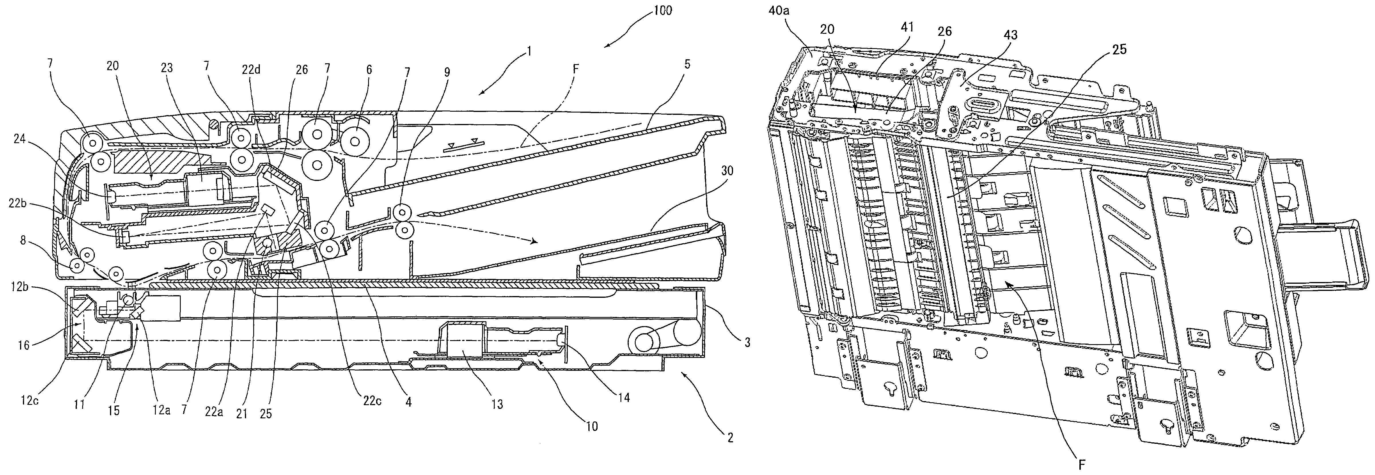
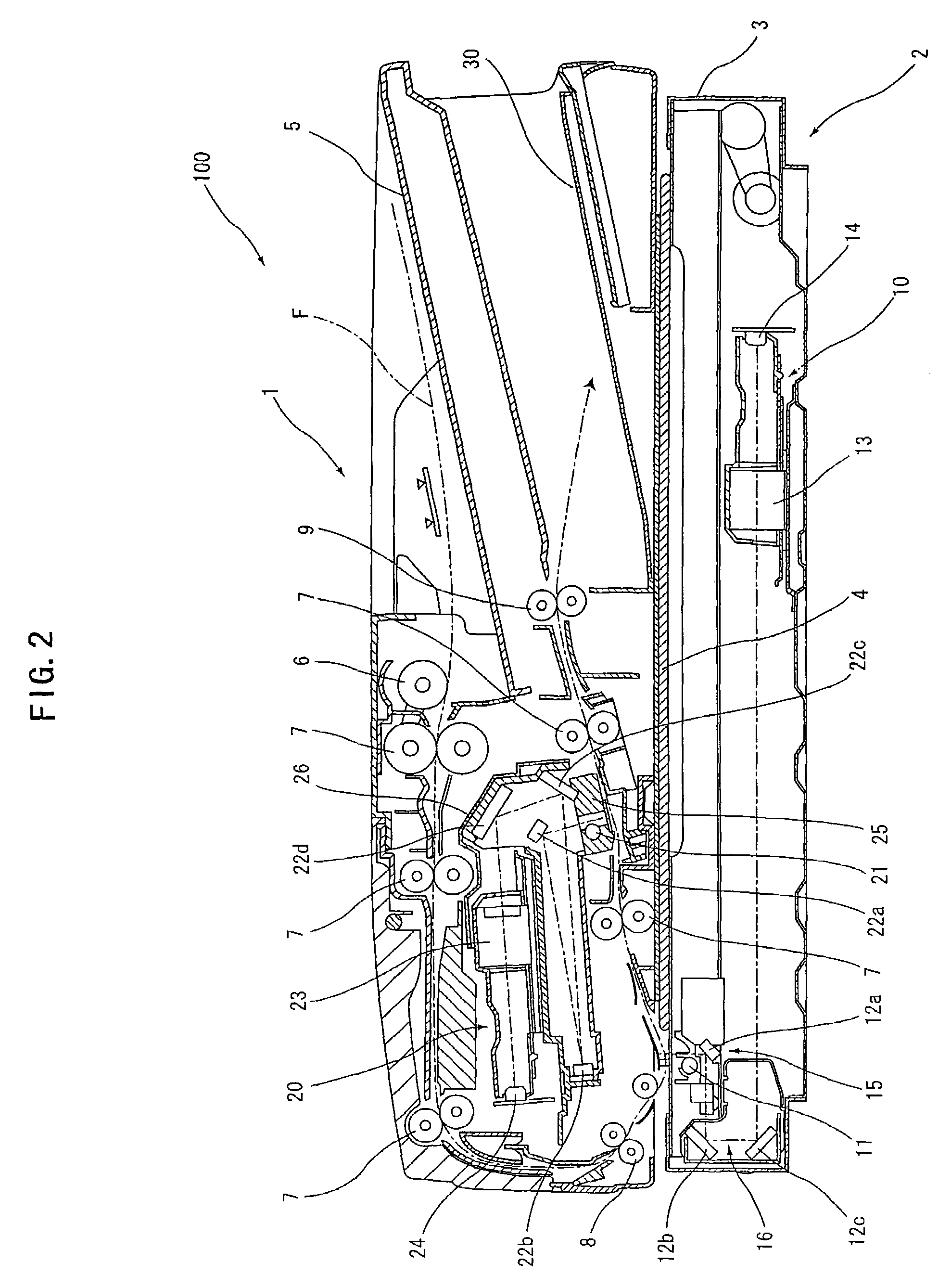
[0036]A document reader according to the present invention comprises: document feeding means for conveying a document along a document conveyance path; first image reading means for reading an image formed on a first side of the conveyed document; and second image reading means for reading an image formed on a second side of the conveyed document, wherein each of the first and second image reading means is of an optical reduction system constituted of a light source, a mirror, a lens and an image sensor, and the second image reading means is unified into a single assembly including at least the mirror, the lens and the image sensor, to be thus detachably attached, as a single unit, to the document feeding means.

[0037]The configuration of the document feeding means in the document reader according to the present invention is not particularly limited as long as the document feeding means can convey the document along the document conveyance path. A specific example is a known automati...


PUM


Abstract

A document reader includes a document feeder conveying a document along a document conveyance path, a first image reader reading an image formed on a first side of the conveyed document, and a second image reader reading an image formed on a second side of the conveyed document. Each of the first and second image readers is of an optical reduction system constituted of a light source, a mirror, a lens and an image sensor. The second image reading means is unified into a single assembly including at least the mirror, the lens and the image sensor, to be thus detachably attached, as a single unit, to the document feeding means. Thus, the document reader can clearly read the images formed on the first and second sides, it requires a short period of time from image reading to image outputting, and its maintenance is readily conducted.

Description

CROSS-REFERENCE TO RELATED APPLICATIONS[0001]This application is related to Japanese application No. 2005-065712 filed on Mar. 9, 2005, whose priority is claimed under 35 USC § 119, the disclosure of which is incorporated by reference in its entirety.BACKGROUND OF THE INVENTION[0002]1. Field of the Invention[0003]The present invention relates to a document reader and, more particularly, to a document reader capable of reading images formed on both sides of a document while the document is automatically conveyed.[0004]2. Description of the Related Art[0005]In the conventional art relevant to the present invention, there has been known a document reader for reading images formed on both sides of a document while the document is automatically conveyed, the document reader comprising a document conveyance path, image reading means of an optical reduction system for reading an image formed on a first side of the document, and an image sensor of a contact type for reading an image formed ...

Claims


Application Information

Patent Timeline
Patent Type & Authority Patents(United States)
IPC IPC(8): H04N1/04G03G15/00
CPCH04N1/00588H04N1/203H04N1/2032
Inventor MORIMOTO, YASUMASA
Owner SHARP KK
Why Eureka
Try Eureka