
Mobile robot for monitoring a subject

Inactive Publication Date: 2005-09-29
KK TOSHIBA
View PDF4 Cites 85 Cited by
  • Summary
  • Abstract
  • Description
  • Claims
  • Application Information

AI Technical Summary

Benefits of technology

[0014] According to another aspect of the present invention, there is provided a method of monitoring a subject, including first detecting a location of a subject by means of at least one sensor mounted on a mobile robot; monitoring movement of the subject based on changes of a detected location of the subject; moving the mobile robot to maintain proximity between the subject and the mobile robot; second detecting at least one characteristic of the subject at one or more locations of the mobile robot; and outputting a signal representative of the detected characteristic of the subject.
[0015] According to another aspect of the present invention, there is provided a mobile robot including a storage device configured to store a map of a locality; a detector configured to detect action of a subject within a detection range; means for maintaining the detector in proximity to the subject; and means for determining

Problems solved by technology

For example, when a user lives in a house by oneself, there may be a case in which, even when an abnormal situation is brought about, the user cannot call for help.

Method used


Image

  • Mobile robot for monitoring a subject
  • Mobile robot for monitoring a subject
  • Mobile robot for monitoring a subject

Examples


first embodiment

[0050] The term “user” and the term “subject” used throughout this application include, but are not limited to, a person, multiple persons, and animals.

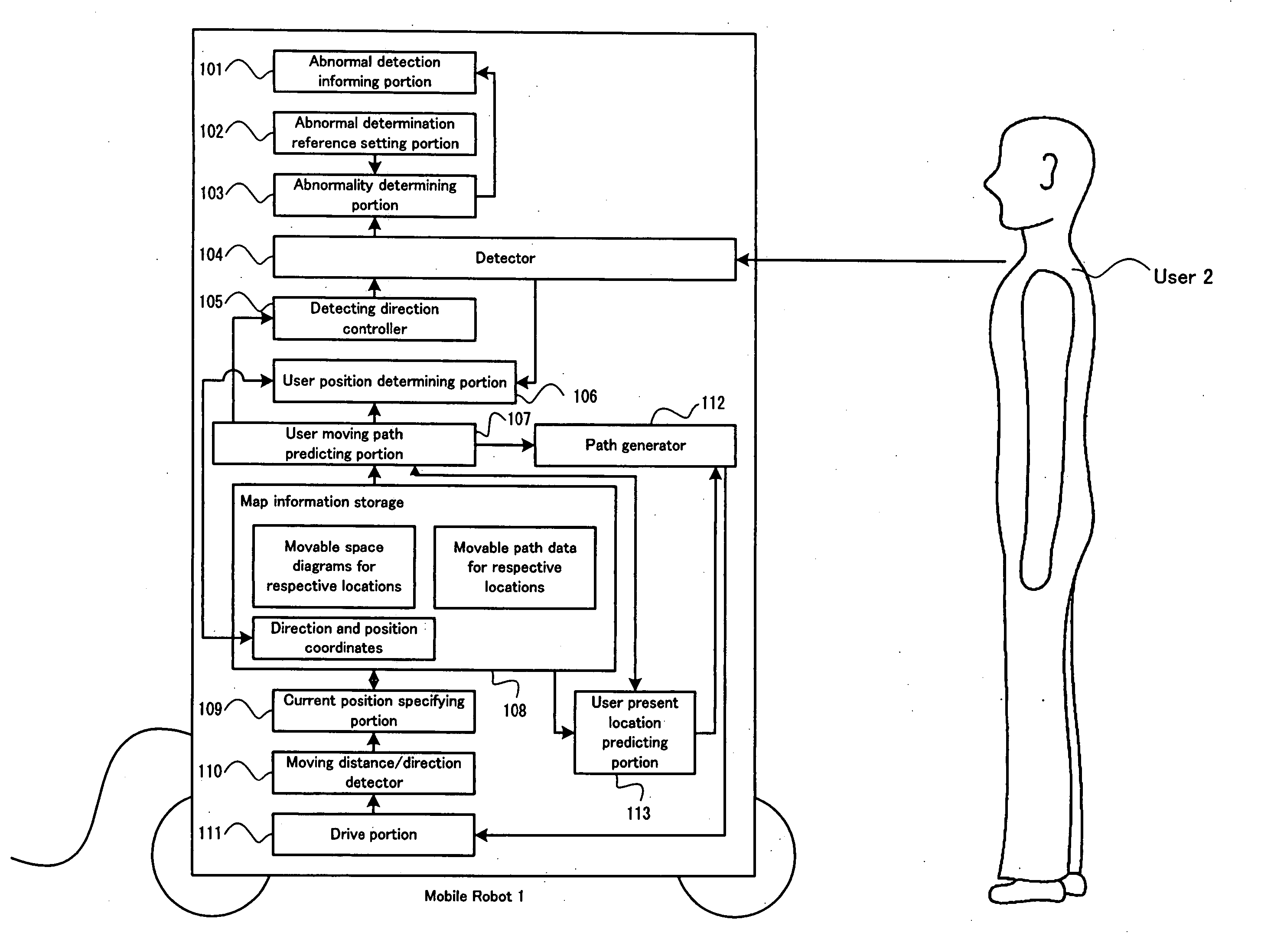
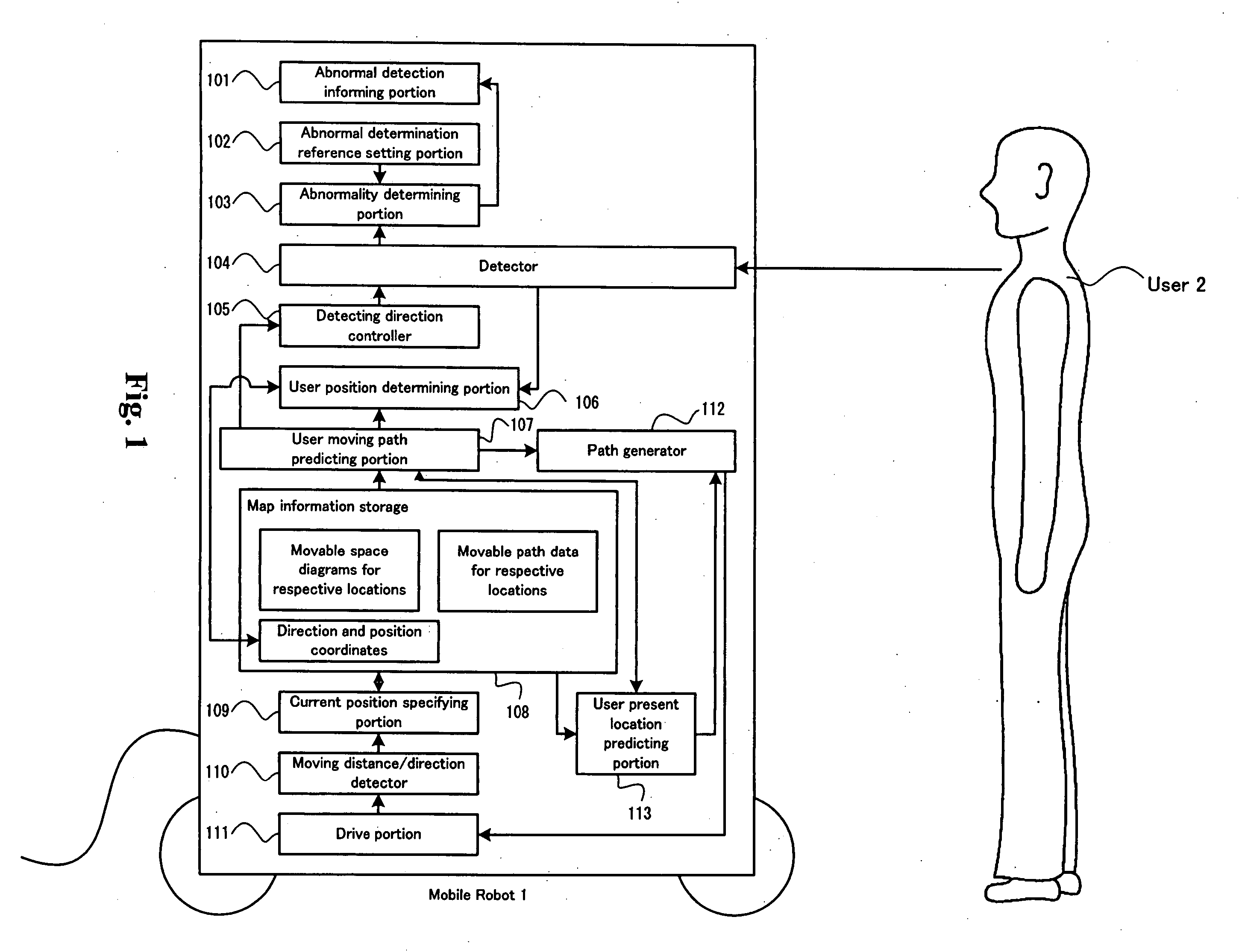
[0051]FIG. 1 is a block diagram showing the components of a mobile robot 1 according to a first embodiment of the invention in schematic form. As shown by FIG. 1, the mobile robot 1 shown in the embodiment includes an abnormal detection informing portion 101, an abnormal determination reference setting portion 102, an abnormality determining portion 103, a detector 104, a detecting direction controller 105, a user position determining portion 106, a user moving path predicting portion 107, a map information storage 108, a current position specifying portion 109, a moving distance / direction detector 110, a drive portion 111, a path generator 112, and a user present location predicting portion 113 for searching to track a user 2. FIG. 1 is not intended to in any way limit the physical location of the above-described portions within th...

second embodiment

[0140] The first embodiment is an example of applying the invention when a movable space of the mobile robot 1 and a movable space of the user 2 coincide with each other. However, in an actual environment, there may be present objects having a height over which the mobile robot 1 cannot pass but the user 2 can tread across. There also may be objects under which the mobile robot 1 can pass, but the user 2 normally moves around. Therefore, the mobile robot 1 according to the second embodiment generates a detour path around a hazard when there is a path on which the mobile robot 1 cannot move although the path is a movable path for the user 2.

[0141]FIG. 23 shows a situation according to the embodiment. Numerals 202, 203, 205 in the drawing designate hazards the same as those illustrated in FIG. 4 in the first embodiment. According to the embodiment, a cushion 2501 is further added on a floor.

[0142] In this case, although the cushion 2501 does not constitute a hazard to the user since...


PUM


Abstract

A mobile robot with a diagram indicating a moving path of a subject and a diagram showing a connection between locations, is capable of generating a path on which a subject is predicted to move from information of the subject detected by a detector, a detecting direction of the detector along the path, or tracking the subject by tracing the path, and predicting a location of a destination of the subject even when the subject has moved to another location. Further, the robot is capable of determining an abnormality based on detected location of the subject.

Description

CROSS-REFERENCE TO RELATED APPLICATIONS [0001] This application is based upon and claims the benefit of priority from the prior Japanese Patent Application No. 2004-052425 filed on Feb. 26, 2004 the entire contents of which are incorporated herein by reference. FIELD OF THE INVENTION [0002] The present invention relates to a mobile robot moved by utilizing map information, particularly to a mobile robot able to track a user by predicting a moving path of the user by utilizing map information. DESCRIPTION OF THE RELATED ART [0003] In recent years, various robots sharing common space with human beings have been presented. Accordingly, it is conceivable to use a robot to monitor whether a user (subject) is safe by tracking the user. For example, when a user lives in a house by oneself, there may be a case in which, even when an abnormal situation is brought about, the user cannot call for help. In this case, when a robot detects an abnormality of the user, the user can be made safe by ...

Claims


Application Information

Patent Timeline
IPC IPC(8): B25J5/00B25J9/16B25J13/00B25J13/08G05D1/02G06F19/00
CPCG05D1/0255G05D1/027G05D2201/0207G05D1/0274G05D1/0272
Inventor SUZUKI, KAORU
Owner KK TOSHIBA
Learn More