Light weight bagless vacuum cleaner

Active Publication Date: 2005-10-13
SHARKNINJA OPERATING LLC
View PDF8 Cites 23 Cited by
  • Summary
  • Abstract
  • Description
  • Claims
  • Application Information

AI Technical Summary

Benefits of technology

[0010] Generally speaking, in accordance with the invention, a light weight upright vacuum cleaner having a cylindrical dirt separation and collection device is provided. The dirt separation and collection device is a substantially cylindrical container with a tangential air inlet at the upper portion and a selectively operable bottom for removal of separated dirt. A combination shroud and filter holder extends from the open top of the container with

Problems solved by technology

In these conventional devices, air is drawn through the appliance by a fan that creates a large pressure drop as the bag fills with dirt.
This increase in pressure drop lowers the cleaning efficiency of the unit.
The location of this weight may affect the ease with which the vacuum cleaner may be used.
Where the weight of the motor is hig

Method used


Image

  • Light weight bagless vacuum cleaner
  • Light weight bagless vacuum cleaner
  • Light weight bagless vacuum cleaner

Examples


Example

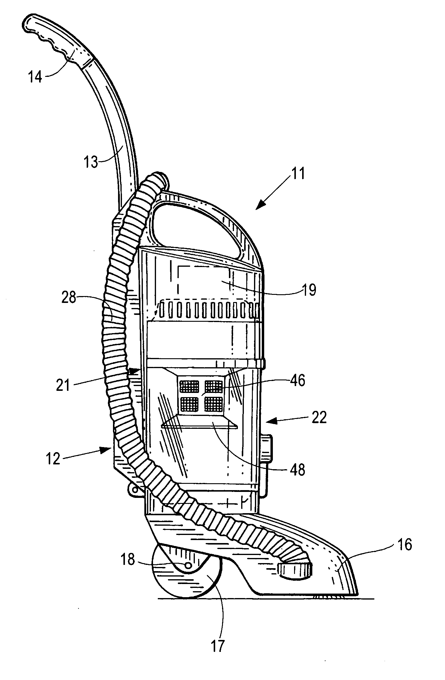
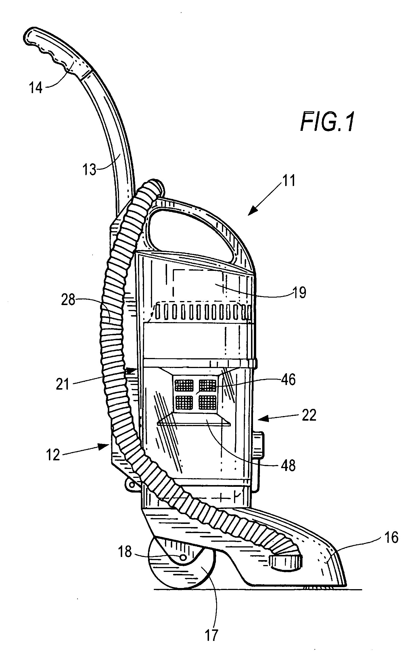
[0025]FIG. 1 shows the main components of a light weight vacuum cleaner 11 constructed and arranged in accordance with the invention. Vacuum cleaner 11 has an elongated housing 12 with an upwardly extending pipe 13 terminating in a user handle 14. An air separation and dirt collection container cavity 21 is formed in the lower portion of housing 12. A suction nozzle 16 is hingedly connected to housing 12 for passing over a surface to be cleaned. A pair of wheels 17 or rollers are mounted at the bottom rear of housing 12 on an axle 18 for ease of displacing over the surface to be cleaned. A vacuum motor 19 is positioned in the upper portion of housing 12 above container cavity 21.

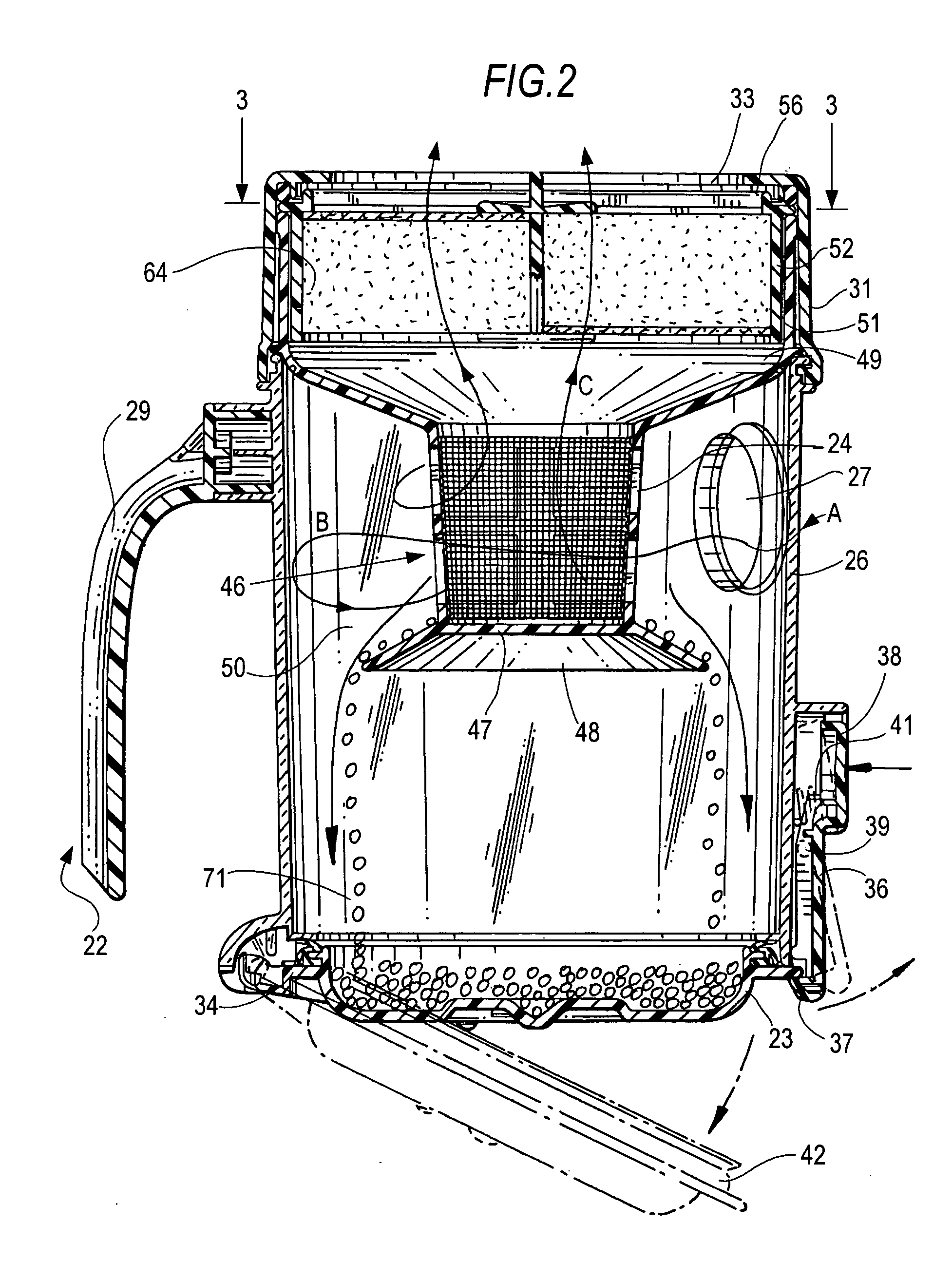
[0026] A selectively removable cylindrical air separation and collection container 22 is positioned in cavity 21 of housing 12. As shown in more detail in FIG. 2, air separation and collection container 22 has a substantially cylindrical sidewall 26 and a cover 31 with a handle 29 and a selectively openable...


PUM

PropertyMeasurementUnit
Fractionaaaaaaaaaa
Fractionaaaaaaaaaa
Weightaaaaaaaaaa

Abstract

A light weight upright vacuum container including a cylindrical cyclonic air separation and dirt collect container with a combination shroud and pleated filter cartridge holder. The container has a tangential air inlet at the upper portion, a closed bottom and an open top leading to a motor positioned in the upper portion of the vacuum cleaner housing provide for improved air separation and dirt collection. The shroud has an open sidewall and a closed bottom with an outwardly and downwardly extending skirt that extends to the about the midpoint of the height of the container. Dirt particles that separate from the air flow above the skirt drop to the lower portion below the skirt. Clean air then exits an open upper portion of the shroud to the suction source above the container. The air exiting the shroud passes through a frusto-conical region and into a radially pleated filter before entering the vacuum motor.

Description

BACKGROUND OF THE INVENTION [0001] The invention relates generally to vacuum cleaners, and more particularly to light weight upright bagless vacuum cleaners including a cylindrical cyclonic separation / dirt collection container with a combined central shroud and filter holder in the container and an outlet at the top of the container with an openable bottom to enhance separation of dirt from the air stream and retention of dirt particles on the bottom of the container. [0002] Cyclonic vacuum cleaners have been known for some time. For example, European Patent No. EP 0 042 723 and U.S. Pat. No. 4,593,429 to James Dyson discloses a vacuum suction cleaning device including two cyclone units in series operating successively to extract dirt particles from an air flow. One of the two cyclones has a substantially frusto-conical shape serving to increase the velocity of the dirt particles so that the cyclone is capable of depositing the fine dust particles in a small diameter collection cham...

Claims


Application Information

Patent Timeline
IPC IPC(8): A47L9/12A47L9/16
CPCA47L9/122A47L9/1666A47L9/1683Y10S55/03
Inventor GREENE, MASONROSENZWEIG, MARK
Owner SHARKNINJA OPERATING LLC
Why Eureka
Try Eureka