

Compact cyclonic bagless vacuum cleaner
- Summary
- Abstract
- Description
- Claims
- Application Information
AI Technical Summary
Benefits of technology
Problems solved by technology
Method used
Image

Examples
Embodiment Construction
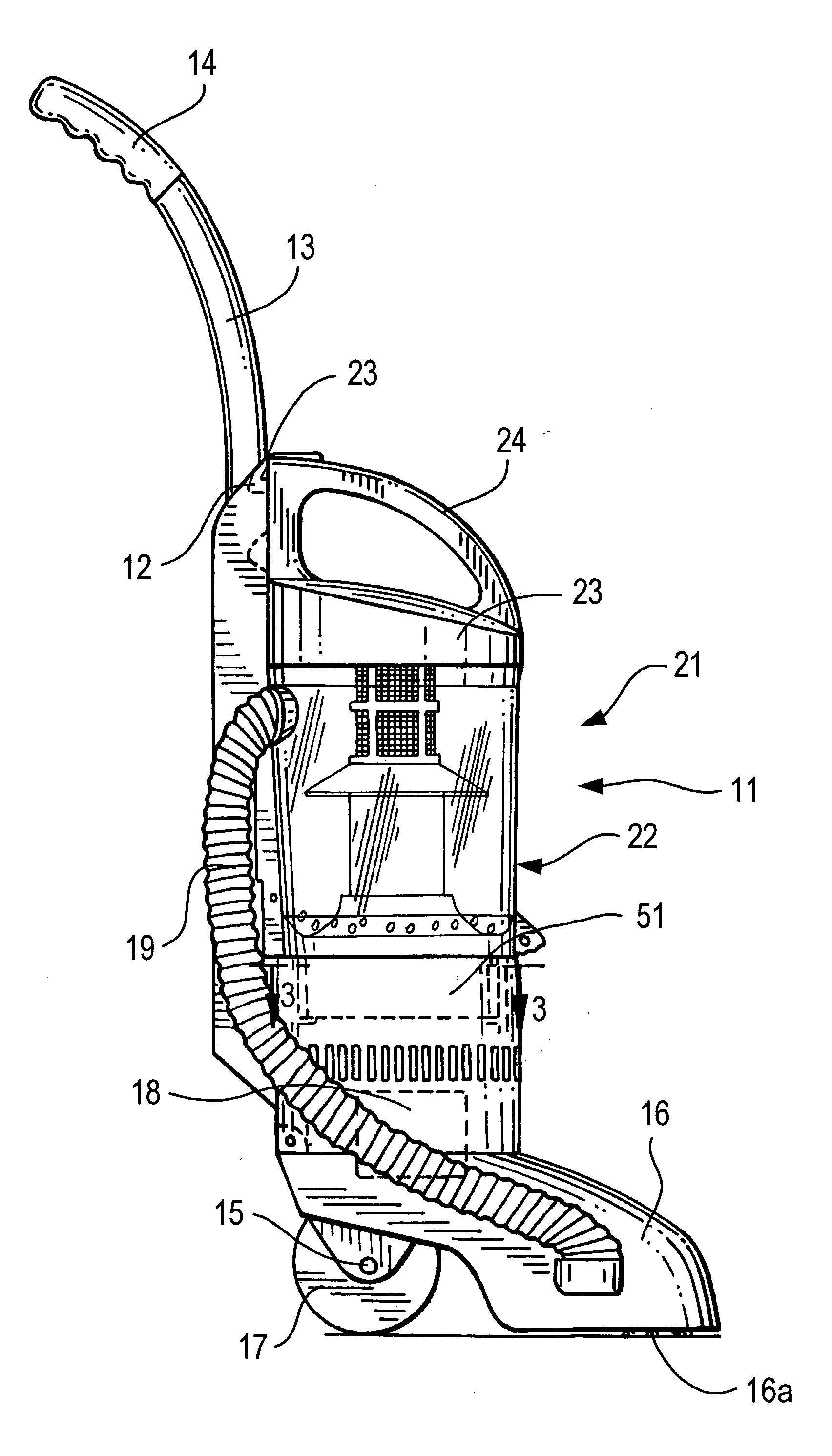
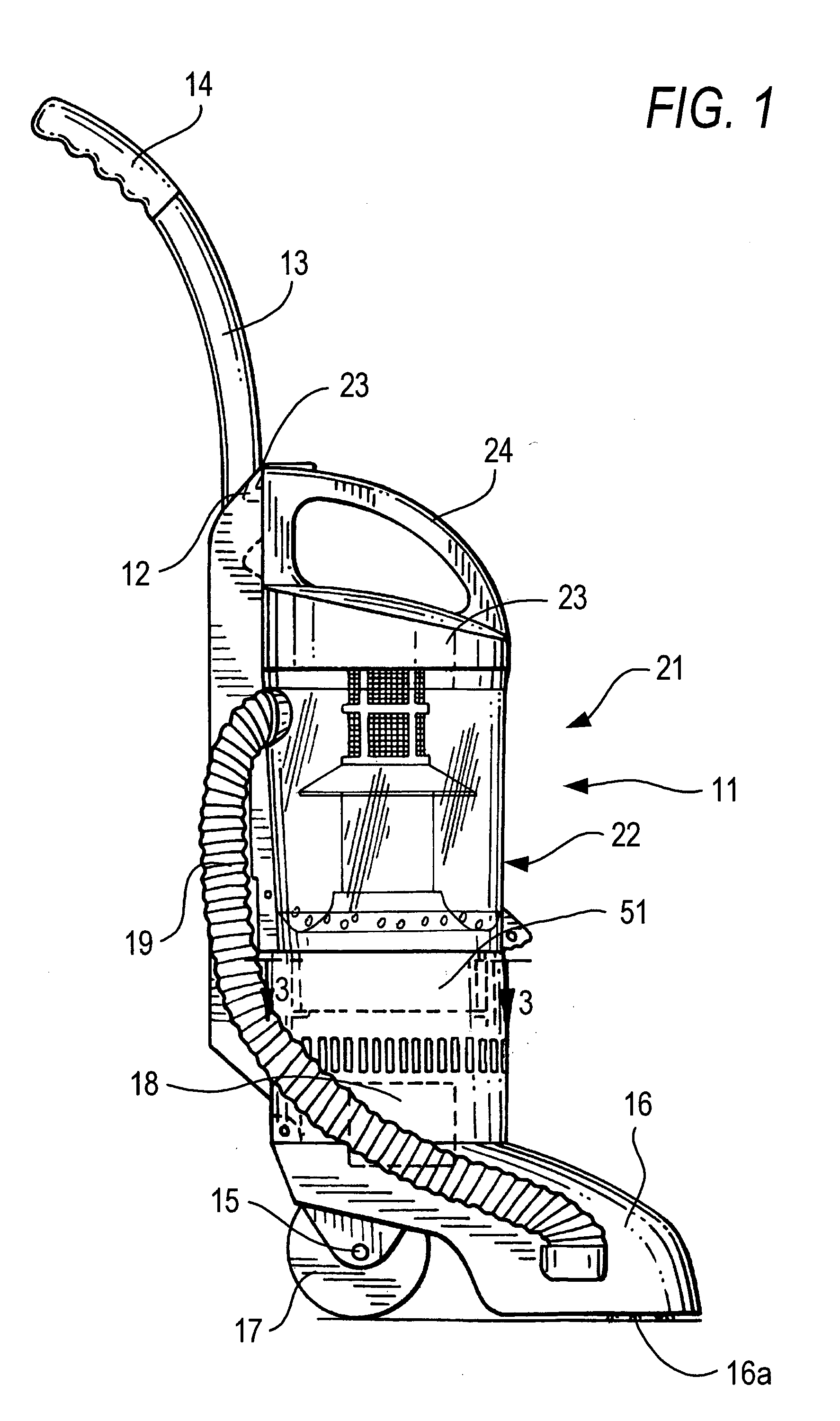
[0022]FIG. 1 shows the main components of a vacuum cleaner 11 having an elongated housing 12 with an upwardly extending pipe 13 terminating in a user handle 14. A suction nozzle 16 is hingedly connected to the bottom of housing 12 for passing over a surface to be cleaned. A selectively removable cylindrical air separation and collection container 21 is positioned in the upper portion of housing 12 above motor 18. A filter cartridge 51 is positioned in housing 12 above motor 18. A conduit 19 provides an airflow connection from nozzle 16 to container 21.
[0023] A pair of wheels 17 or rollers are mounted to an axle 15 at the rear lower portion of housing 12 for ease of displacing vacuum cleaner 11 over the surface to be cleaned. A vacuum motor 18 is positioned in the lower portion of housing 12 above wheels 17. This provides a low center of gravity to vacuum cleaner 11. By keeping a low center of gravity, the stability of a compact vacuum cleaner 11 when operated by a user holding hand...
PUM
| Property | Measurement | Unit |
|---|---|---|
| Fraction | aaaaa | aaaaa |
| Fraction | aaaaa | aaaaa |
| Flow rate | aaaaa | aaaaa |
Abstract
Description
Claims
Application Information