
Staple cartridge for electric stapler

a technology of stapler and stapler, which is applied in the direction of stapling tools, manufacturing tools, nailing tools, etc., can solve the problems of stricken staples being buckled and jammed, finger contact with staple end portions, and inability to meet staples, etc., to achieve safe and easy removal, low manufacturing cost of staple cartridges, and simple structure of staple cartridges

Inactive Publication Date: 2005-10-13
MAX CO LTD
View PDF16 Cites 0 Cited by
  • Summary
  • Abstract
  • Description
  • Claims
  • Application Information

AI Technical Summary

Benefits of technology

[0007] It is a first object of the present invention to provide a staple cartridge characterized in that: jammed staples, which are jammed in the staple striking passage, can be safely and easily removed; and the structure of the staple cartridge is simple as a disposable cartridge, and the manufacturing cost of the staple cartridge is low.
[0008] It is a second object of the present invention to provide a staple cartridge characterized in that: the spring piece in the accommodating portion can be easily removed from the staple magazine, the staples of which have been consumed, without using a tool, so that the staple cartridge can be easily classified and recovered or discarded.

Problems solved by technology

However, in the stapler described above, the thickness of sheets of paper to be bound is restricted by the size of staple to be used.
Therefore, the stricken staple is buckled and jammed in the striking passage.
In the conventional cartridge, since the face plate is pivotally attached to the forward end portion of the staple cartridge, when the face plate is turned to remove the jammed staple with a finger, the finger may be contacted with an end portion of the staple and may be injured.
Therefore, the structure of the conventional cartridge is complicated.
Therefore, the manufacturing cost of the cartridge having the above complicated structure is raised.
This work to pick up the spring piece is complicated and dangerous.
Accordingly, it is impossible for the conventional staple cartridge to use resources effectively and contribute to the prevention of environmental destruction in the case of discarding the used staple cartridge.

Method used


Image

  • Staple cartridge for electric stapler
  • Staple cartridge for electric stapler
  • Staple cartridge for electric stapler

Examples


first embodiment

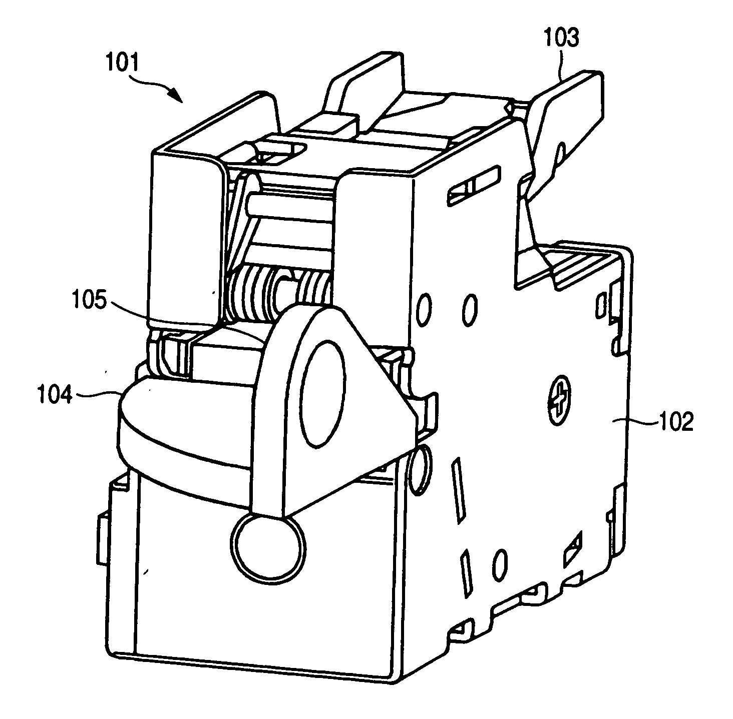
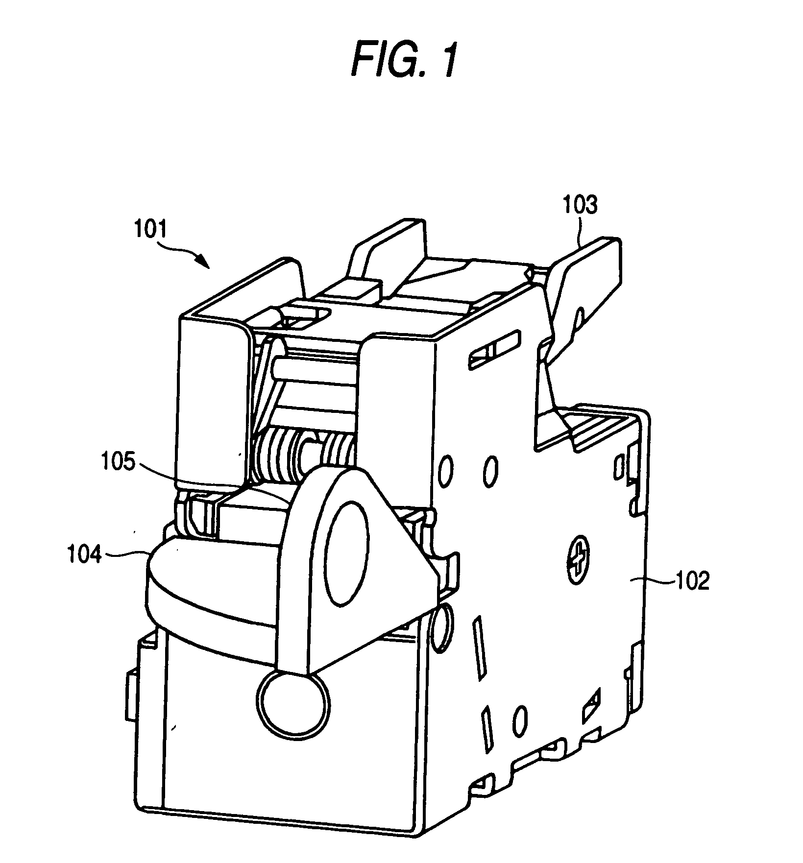
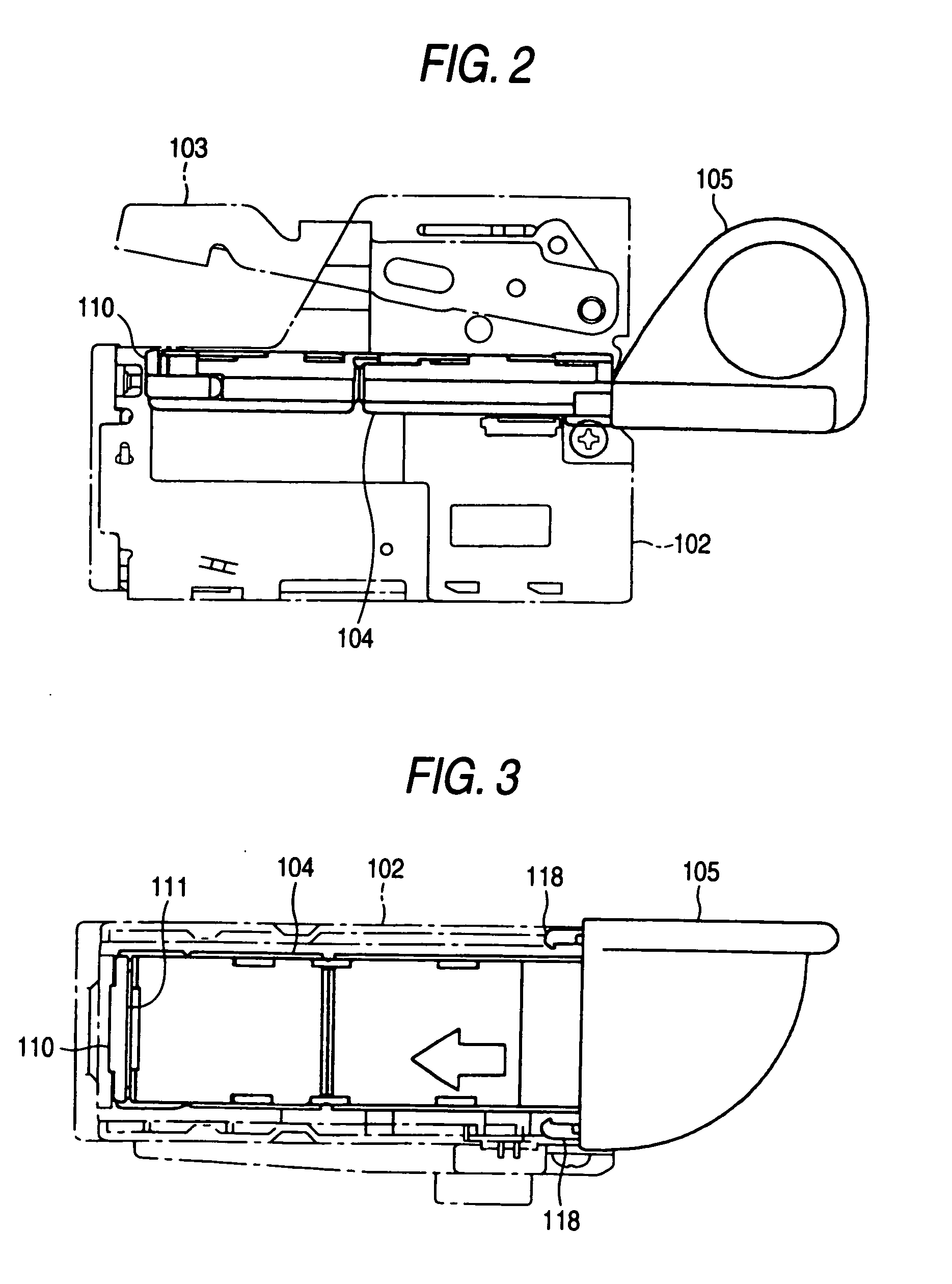
[0025] Referring to the embodiment shown in the drawings, the present invention will be explained below. FIG. 1 is a view showing an electric stapler to which the staple cartridge of the present invention is attached. The electric stapler of this embodiment is incorporated into an apparatus such as a copying machine, printer or facsimile. A predetermined number of sheets of paper, which have been copied, printed or received by facsimile, are automatically stapled by this electric stapler of the built-in type. The electric stapler 101 includes: an electric motor arranged in a lower portion of the frame 102, which is a drive source of the electric stapler 101; a driver driven by the electric motor; and a forming plate for forming the staples. In an upper portion of the frame 102, the clincher arm 103 is pivotally supported, which bends leg portions of the staple that has penetrated sheets of paper to be bound when the staple has been stricken by the driver.

[0026] As shown in FIGS. 2 a...

second embodiment

[0030] Next, referring to the embodiment shown in the drawings, the present invention will be explained below. FIG. 9 is a view showing an electric stapler to which the staple cartridge of the present invention is attached. The electric stapler of this embodiment is incorporated into an apparatus such as a copying machine, printer or facsimile, and a predetermined number of sheets of paper, which have been copied, printed or received by facsimile, are automatically stapled by this electric stapler of the built-in type. The electric stapler 201 includes: an electric motor arranged in a lower portion of the frame 202, which is a drive source of the electric stapler 201; a driver driven by the electric motor; and a forming plate for forming the staples into a C-shape. In an upper portion of the frame 202, the clincher arm 203 is pivotally supported, which bends leg portions of the staple that has penetrated sheets of paper to be bound when the staple has been stricken by the driver.

[00...


PUM


Abstract

A staple cartridge includes: a cartridge body for accommodating a large number of staples; and a faceplate provided at a front end portion of the cartridge body, for forming a striking passage (211) of striking a staple by a driver, wherein support pieces are integrally formed from both side edges of the face plate to the rear, engaging bosses formed in the support pieces are engaged with recess portions formed on both sides of the front end portion of the cartridge body (206), and the face plate is slidably and pivotally supported by the cartridge body (206). In the cartridge body (206) and cover (209), the small thickness grooves (215), (216), by which the staple cartridge (204) is bent into two pieces, are formed on the circumference of the staple accommodating portion.

Description

TECHNICAL FIELD [0001] The present invention relates to a staple cartridge for an electric stapler, in which a large number of staples are accommodated, detachably attached to the electric stapler body. The present invention also relates to a staple cartridge for an electric stapler having a face plate on which a striking passage for striking staples is formed. BACKGROUND ART [0002] In an electric stapler for successively striking staples, which are charged into a magazine, by driving a driver with a motor, the following cartridge type electric stapler is well known. In order to make it easy to charge staples into the magazine, a staple cartridge which accommodates a large number of staples is attached to the magazine of the electric stapler, and the staples in the staple cartridge are successively stricken by the driver so that binding can be accomplished by the staples. [0003] The staple cartridge includes: an accommodating portion for accommodating a large number of staples; and ...

Claims


Application Information

Patent Timeline
Patent Type & Authority Applications(United States)
IPC IPC(8): B27F7/38
CPCB27F7/38B25C5/16
Inventor HAKOZAKI, KATSUYASATO, HIROSHIYAGI, NOBUAKISIMIZU, TOSHIO
Owner MAX CO LTD
Learn More