Range extractor hood

a range extractor and hood technology, applied in the field can solve the problems of inconvenient user and effort expended by users of range extractor hoods

Inactive Publication Date: 2014-12-23
BOSCH SIEMENS HAUSGERATE GMBH
View PDF32 Cites 7 Cited by
  • Summary
  • Abstract
  • Description
  • Claims
  • Application Information

AI Technical Summary

Benefits of technology

[0005]An object underlying the present invention is therefore to create a range extractor hood in which the filter can be safely and easily removed and, in particular, requires minimum interaction on the part of the user.
[0013]The inventive construction of the range extractor hood makes it possible to remove the filter element from the range extractor hood in a simple and reliable manner. In particular, due to the location of the releasing device on the screen, the filter can be of a particularly simple construction. In particular, no actuating element such as a sliding or lever handle on the filter element is necessary. In the simplest case, in order to remove the filter element from the range extractor hood, the user of the range extractor hood has only to remove the existing connection from the filter element to the screen via the pivot bearing. This can be effected by simple removal. Furthermore, since in addition to the locking means the filter is retained on the screen by the pivot bearing, uncontrolled fall-out can be prevented following release of the locking device.
[0014]According to one embodiment, the releasing device is actuated by movement of at least one part of the screen. The part of the screen that is moved for actuation of the releasing device can be a component part of the screen or a means located in the screen. Release of the filter element is further simplified by triggering the releasing device by moving a part of the screen. Preferably, the part of the screen which has to be moved in order to actuate the releasing device is located on the front side of the screen or forms at least one part of the front side of the screen. The screen, or at least its front side, faces the user of the range extractor hood and can therefore be easily reached by the user. In particular, in contrast to the filter element which is usually provided in the underside of the screen, the user can easily access the front side of the screen and thus initiate the filter replacement or removal processes.
[0015]According to one embodiment, the releasing device is located, at least partially, at a distance from the locking means. Preferably, the releasing device engages the locking means that is provided on the filter element, or at least acts upon said filter element. Due to the arrangement of the releasing device in the screen, at least one part of the releasing device can of course be located at a distance from the locking means. For example, at least one part of the releasing device can be located on the front side of the screen or on the rear side of the screen. As a result of this, the releasing device can be protected against contamination which occurs at the filter element, in particular grease or liquid deposits, or is at least less exposed to these.
[0022]According to one embodiment, the range extractor hood has at least one damping means for damping the motion of the pivot bearing. The damping means can be a rotary damper that can be provided directly on the pivot bearing, for example in a seat on the screen. Alternatively, however, the damping means can also include a lever structure in which damping elements in the form of springs can be provided, for example. The lever structure engages the filter element at a distance from the pivot bearing. Due to the presence of a damping means, the filter element can be safely swung out and injury to the user avoided.

Problems solved by technology

A drawback of this locking device is that the user of the range extractor hood has to expend some effort in attaching this device to the appliance.
In addition, releasing the locking device requires the hinged filter cartridge to be grasped from behind, which can be inconvenient for the user where the filter cartridges are severely soiled.

Method used


Image

  • Range extractor hood
  • Range extractor hood
  • Range extractor hood

Examples


first embodiment

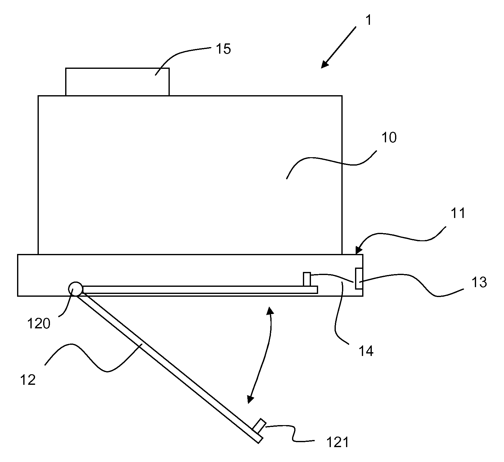
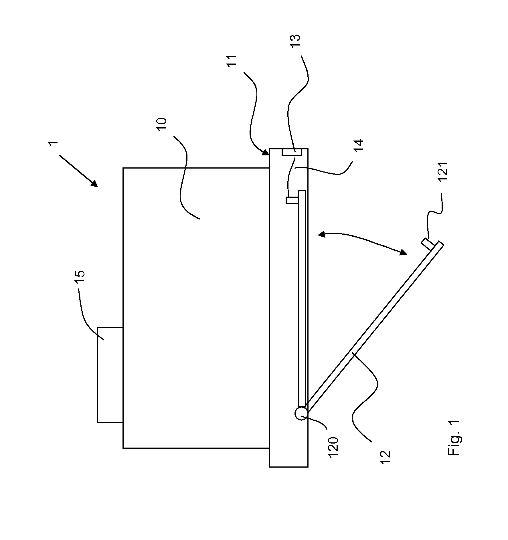
[0030]In the first embodiment shown, an operating element 13 via which a releasing device 14 can be actuated, is provided in the front side of the screen 11. The operating element 13 is considered to be part of the releasing device 14. By actuating the operating element 13, which can be a button, for example, the connection in the form of the locking means 121, between the filter element 12 and the screen 11, can be released via the releasing device 14. In the embodiment shown the releasing device 14 can be a mechanical connection between the operating element 13 and the locking means 121 in the installed position of the filter element 12. If the locking means 121 is a latching lug, for example, then the releasing device 14 can act on the latching lug until this disengages from the latching recess in the screen 11.

[0031]By releasing the locking device, the filter element 12 is brought into the withdrawn position, also shown in FIG. 1. For this, the filter element 12 is swung downwar...

second embodiment

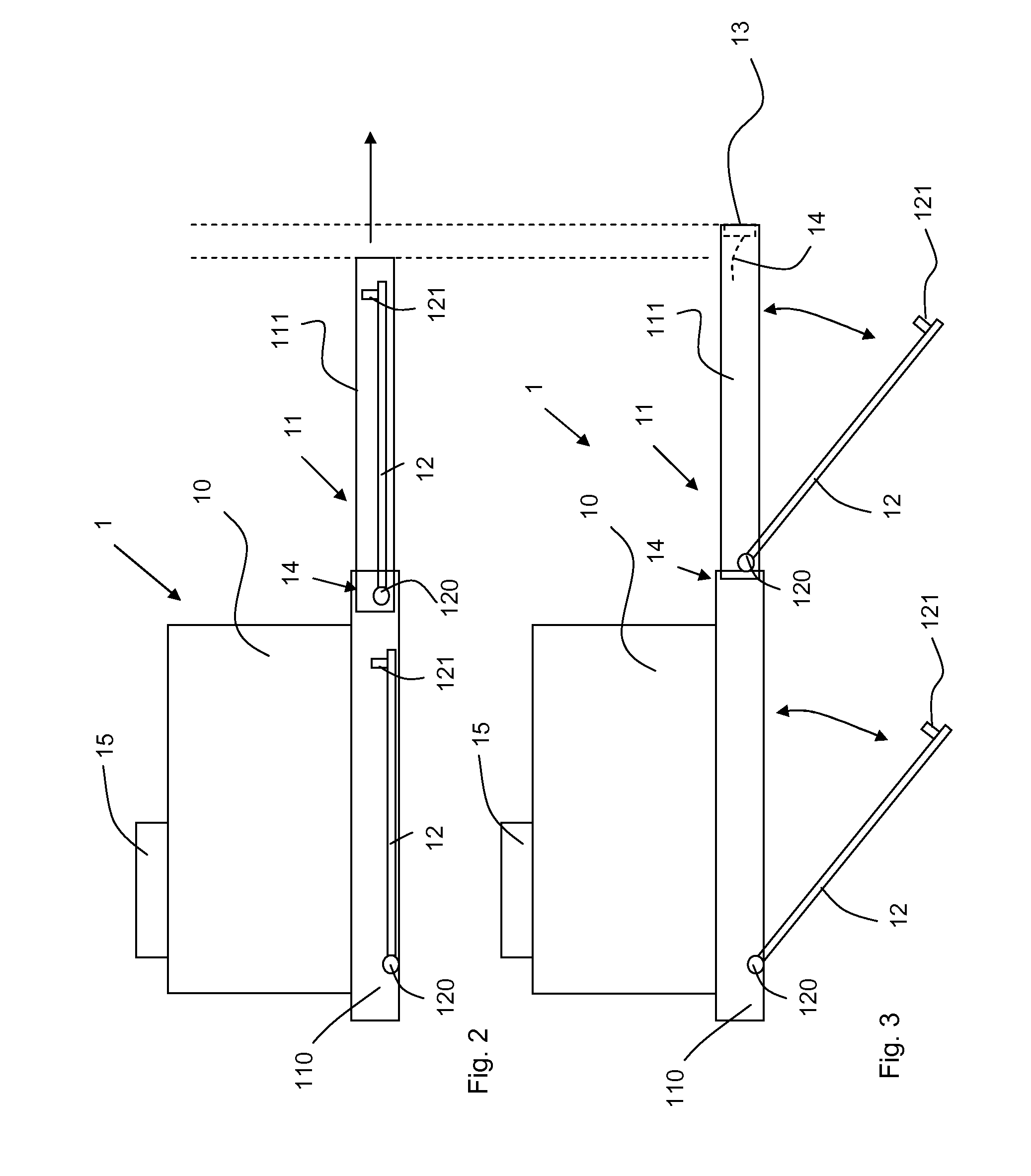
[0032]the inventive range extractor hood is shown in FIGS. 2 and 3.

[0033]The second embodiment differs from the first embodiment in that the screen 11 is embodied in a number of parts. In the second embodiment the screen 11 consists of a framework 110 that is permanently joined to the housing 10, and a pull-out drawer 111 that is attached to the framework 110 in a sliding manner. In particular, the pull-out drawer 111 can be withdrawn forwards in relation to the framework 110. FIG. 2 shows an operating position of the pull-out drawer 111. In this position the pull-out drawer 111 has been withdrawn. Naturally, the rear end of the pull-out drawer 111 is still in the framework 110 of the screen 11. The pull-out drawer 111 is guided in the framework 110 via a guide which, in particular, includes lateral supports. In the embodiment shown, a filter element 12 is indicated in each case in the framework 110 and in the pull-out drawer 111. Preferably of course a plurality of filter elements ...


PUM

PropertyMeasurementUnit
movementaaaaaaaaaa
distanceaaaaaaaaaa
dampingaaaaaaaaaa

Abstract

A range extractor hood includes a screen, at least one filter element and at least one pivot bearing which swingably supports the at least one filter element on the screen. At least one locking member retains the at least one filter element to the screen. Located on the screen is a releasing device for, at least partially, releasing the locking member and retention of the filter element.

Description

BACKGROUND OF THE INVENTION[0001]The invention relates to a range extractor hood.[0002]At least one grease filter is provided on range extractor hoods which are usually used in kitchens. This filter has to be removed at regular intervals to be cleaned or to be replaced by a new filter.[0003]It is known from the prior art for filter cartridges to be provided with a slide or twist handle. In this case two rods, for example, are displaced by sliding or twisting the handle strap provided on the twist handle. In the mounted position of the filter cartridge, the rods of the handle, together with in particular, stationary rods which are located on the side opposite to the bars of the handle on the filter or on the range extractor hood, retain the filter in its installed position. The sliding rods, and where applicable the stationary rods, are inserted into corresponding cut-outs in the range extractor hood. Locking devices are known which prevent the filter cartridge from falling out of th...

Claims


Application Information

Patent Timeline
Patent Type & Authority Patents(United States)
IPC IPC(8): F24C15/20
CPCF24C15/2035Y10S55/36
Inventor BRO.BETA.MANN, ANNAEHRENSBERGER, JULIAGOCZOL, ANDRZEJHEGENDORFER, MICHAELHIBELT, ROBERTKOTLINSKI, THOMASMETZ, DANIELPANTEN, STEFANRUTSCH, KLAUS-HEINERSCHNEIDER, ILKAWELLHAUSEN, JULIAWILDE, THOMAS
Owner BOSCH SIEMENS HAUSGERATE GMBH
Why Eureka
Try Eureka