
Liner retainer device

a retainer device and liner technology, applied in the direction of flexible container closure, machine support, refuse gathering, etc., can solve the problems of prone to collapse or slip back into the container, health problems, dangers, etc., and achieve the effect of easy application and easy disassembly

Inactive Publication Date: 2005-05-17
TIPP RAYMOND P +1
View PDF29 Cites 17 Cited by
  • Summary
  • Abstract
  • Description
  • Claims
  • Application Information

AI Technical Summary

Benefits of technology

[0008]A primary object of the liner retainer of the present invention is to provide a tightening and constricting means for the retention of the folded upper portion of a liner disposed on the exterior of the rigid waste container to prevent the folded upper section of the liner from collapsing or slipping back into the waste container as refuse or waste is deposited therein and that does not suffer from the above enumerated deficiencies. Another object is to provide such an elongated adhesive strip body that is fabricated from thin, flexible plastic or paper material with a paper release covering adhered to the second side where the adhesive is applied thereto. A further object is to provide such a single use retaining device that is inexpensive and can be easily applied to such liners, which can thereafter easily be detached to release the tension and constriction provided and which can thereafter be used to secure closure of the liner for safe and sanitary disposal.
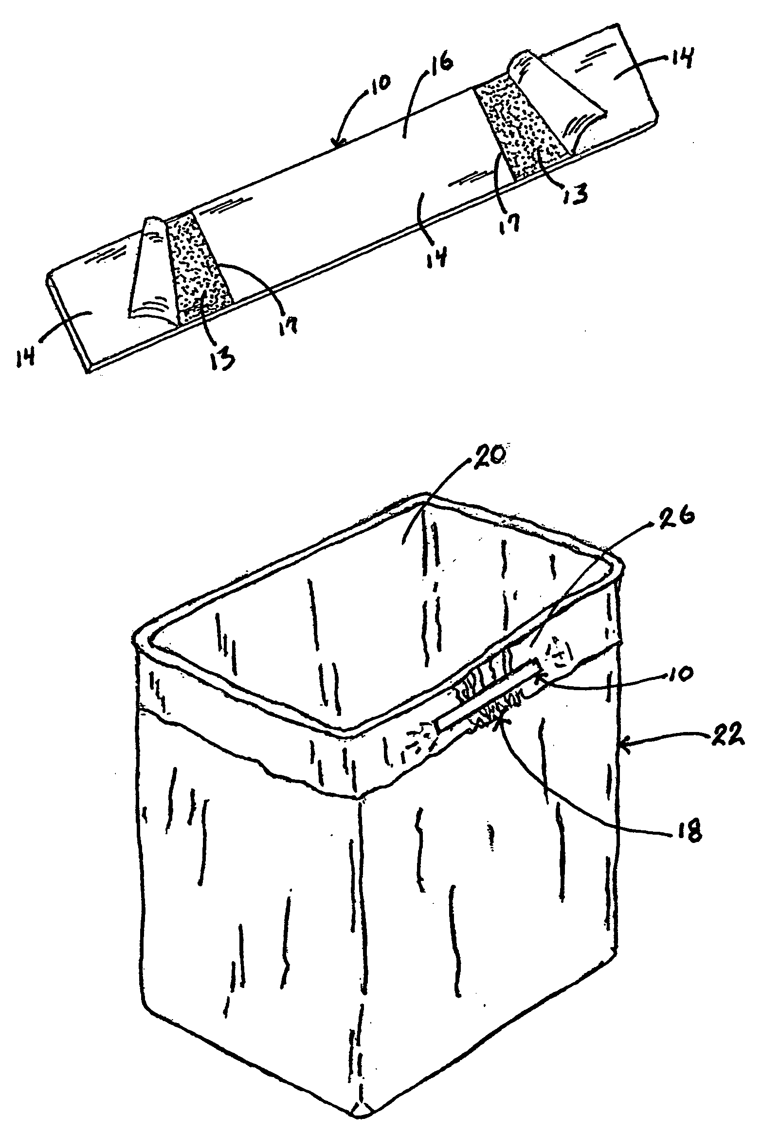
[0010]In accordance with the present invention, there is provided a liner retainer incorporating a quick, inexpensive, disposable and reliable flexible elongated adhesive surface means pressurably attachable to the upper portion of the folded upper section for stretching and constricting the folded upper section of the liner tightly around the top of a waste container, thereby retaining and constricting the folded upper section of the liner in place so that the liner does not collapse or slip back into the waste container as it is being filled. After the waste container / liner is used to the extent that the refuse or waste is to be disposed of, the adhesive surface retaining means of the present invention is easily detached from the surface of the liner, or the non-attached mid-section thereof can be torn away, thereby releasing the constricting tension to the folded upper section of the liner so that the liner with refuse or waste deposited therein can be safely and easily removed in the liner from the waste container. The paper release covering mid-section portion of the liner retainer body is then removed or peeled to be used to secure the closure of the top of the liner, safely encapsulating the refuse or waste therein for easy and sanitary disposal.

Problems solved by technology

The liner, if not restrained or constricted has the tendency to collapse or slip back into the container as the container is being filled.
The liner thus disposed becomes part of the refuse or waste or it presents an unhealthy and disgusting chore to dig it out of the waste container as well as the misplaced refuse or waste to be properly placed in the liner for ultimate disposal means.
In a hospital or other medical facility venue, the propensity of such liners to collapse or slip presents a great health problem and danger.
Disadvantages exist with this arrangement if the liner is not secured to avoid the folded upper section of the liner from collapsing or slipping back into the waste container when refuse or waste is deposited in the lined waste container.
When this occurs, the liner becomes part of the refuse or waste, the waste container is soiled and the removal of the liner as intended with the refuse or waste contained therein is compromised.
This has not proven to be practical as the liner oft times splits or tears and there are numerous sizes and configurations of waste containers so there is no size fits all, 2) inserting the folded over upper section of the liner into a slot of an accumulator and knotting the accumulator to stretch the folded over upper section of the liner around the top of the container as set forth in Julian U.S. Pat. No. 6,012,686, 3) a clip to secure the liner / bag against the waste container as set forth in U.S. Pat. No. 6,343,409, 4) rubber bands or cords, rigid and flexible straps, ties of various sorts, weights, strings or cords made a part of the liner / bag, and an adhesive strip means which is part of the liner as set forth in U.S. Pat. No. 6,029,844.
Many persons employ hand tied knots of the liner upper section which is mostly ineffective.

Method used


Image

  • Liner retainer device
  • Liner retainer device
  • Liner retainer device

Examples


Embodiment Construction

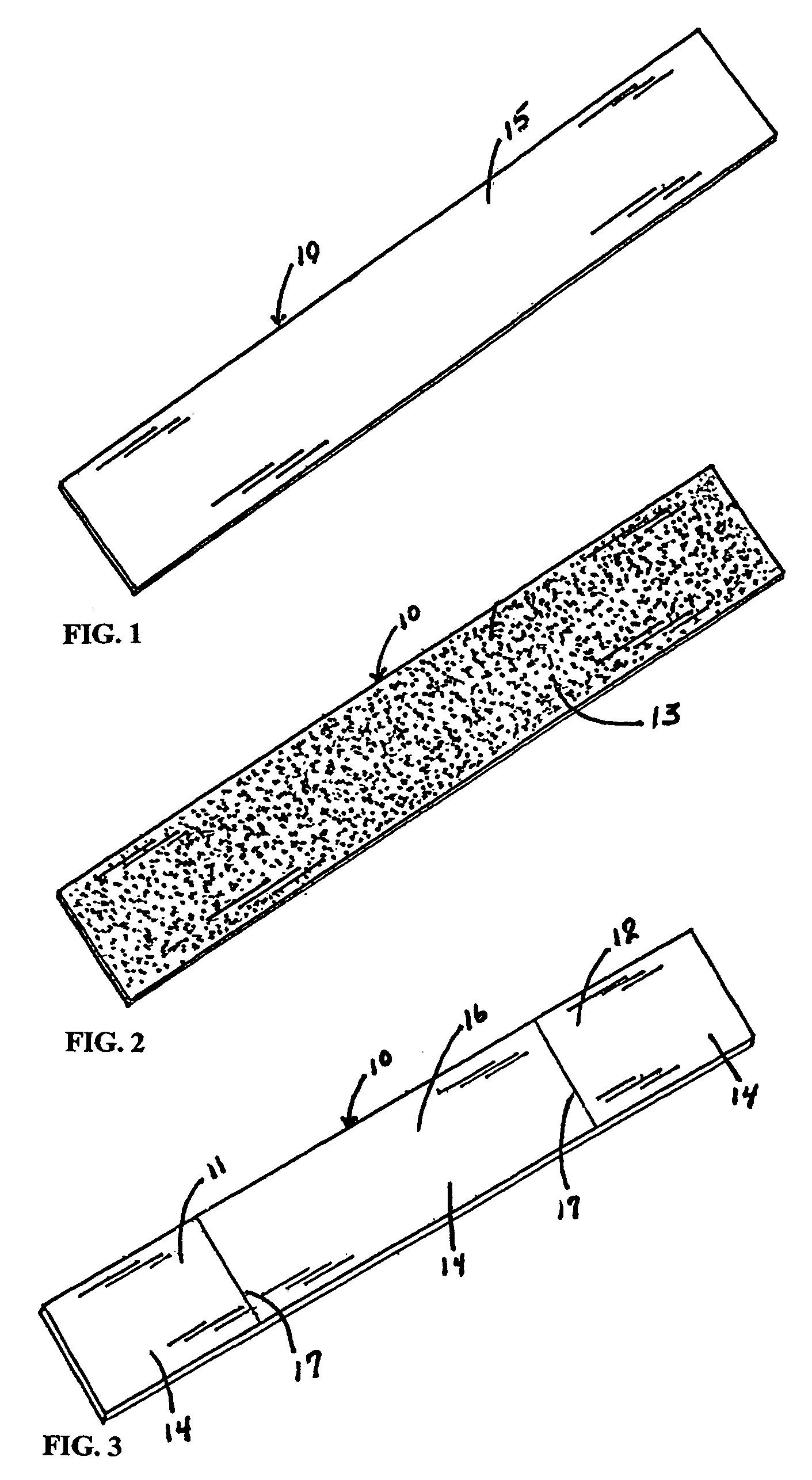
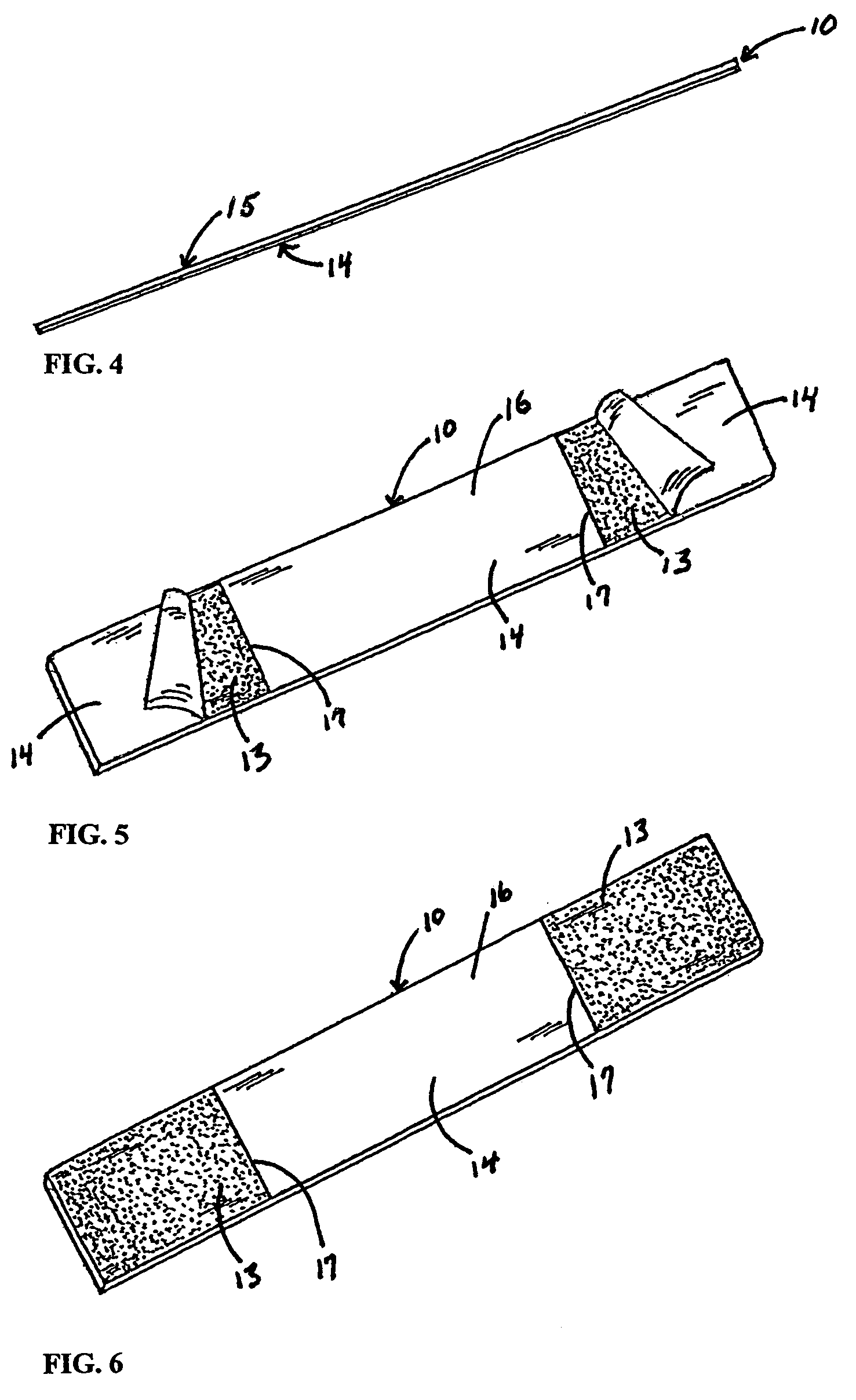
[0034]Referring now to the drawings wherein the showings are for purposes of illustrating embodiment of the present invention only, and not for the purposes of limiting the same, FIG. 1, 3 illustrates the first side 15 of the liner retainer body 10 constructed in accordance with the present invention. The liner retainer body 10 is formed of a plastics or paper material that is sufficiently elastic that the liner retainer body 10 can conform to the bulk of the gathered material and surface variations of a waste container 22. The second side of the liner retainer 19 has applied to it pressure sensitive adhesive 13, FIG. 2, which has a paper release covering 14 adhered to it. FIGS. 4,5,6,9 and 10. The paper release covering 14 is scored 17 selectively illustrating that the first end portion 11 of the liner retainer body 10 comprises a designated portion 11 of the liner retainer body 10, the second end portion 12 of the liner retainer body 10 comprises a comparable designated portion 12...


PUM

PropertyMeasurementUnit
Flexibilityaaaaaaaaaa
Elasticityaaaaaaaaaa
Tensile strengthaaaaaaaaaa

Abstract

A liner retainer device for attachment to a folded upper section of a liner of a waste container comprises an elongated flexible unitary body having a first side which is printable and a second side upon which is applied pressure sensitive adhesive with a paper release covering adhered thereto. The paper release covering is scored so as to be divided into three segments, one defining a first end portion, one defining a second end portion and one defining a mid-section portion. The liner retainer body is formed of a thin material having sufficient elasticity to be disposed over uneven surface and material without exceeding the elastic limit of the material and with sufficient tensile strength to resist breaking or tearing. The paper release covering can be selectively peeled and removed to expose the adhesive thereunder sufficient to be useful as and for an attachment and securing means for the retention of liners for waste containers and an aid for the closure of the liner thereafter for disposal of the used liner.

Description

CROSS REFERENCE TO RELATED APPLICATIONS[0001]This application is a continuation-in-part of design application Ser. No. 29 / 169,748, filed Oct. 28, 2002 now U.S. Pat. No. D, 489,154 entitled “Retention Device for Wastebasket and Container Liners.” The disclosure of this application is hereby incorporated by reference in its entirety, including all the figures.FIELD OF THE INVENTION[0002]This invention relates to devices to be applied to liners for waste baskets, trash cans and other similar containers to lock, constrict and secure the plastic film liner from collapsing or slipping into the container when material is put into the cavity of the liner which is then selectively releaseable and applied to secure closure of the open end of the used liner for disposal. More particularly, this invention relates to such devices adapted to be applied or attached to the liner after a liner is placed or inserted in the container of the type found in homes, offices, hospitals, other medical facili...

Claims


Application Information

Patent Timeline
IPC IPC(8): B65F1/04B65F1/06
CPCB65F1/06Y10T156/1085
Inventor TIPP, RAYMOND P.TIPP, RONALD F.
Owner TIPP RAYMOND P
Learn More