
Information processing method, information processing device, image output device, information processing program, and recording medium

a technology of information processing and image output, which is applied in the direction of cathode-ray tube indicators, instruments, and device coding details, etc., can solve the problem of increasing the possibility that the touch panel could misidentify the selection of users, and the design of the pictograph cannot be changed according to a content,

Active Publication Date: 2005-10-13
SHARP KK
View PDF5 Cites 86 Cited by
  • Summary
  • Abstract
  • Description
  • Claims
  • Application Information

AI Technical Summary

Benefits of technology

[0067] Moreover any one of, some of, or all of the plurality of keys displayed on the screen may be the target key(s). Further, the effect of the invention mentioned above may be also attained by changing the detection region of the target key without changing the key display region of the target key. However, the key display region of the target key may be expanded / shrunk in accordance with the detection region.
[0068] In the following, the information processing device according to the present invention that attains the above effect, and the information processing method using the information processing device are specifically described. First Embodiment
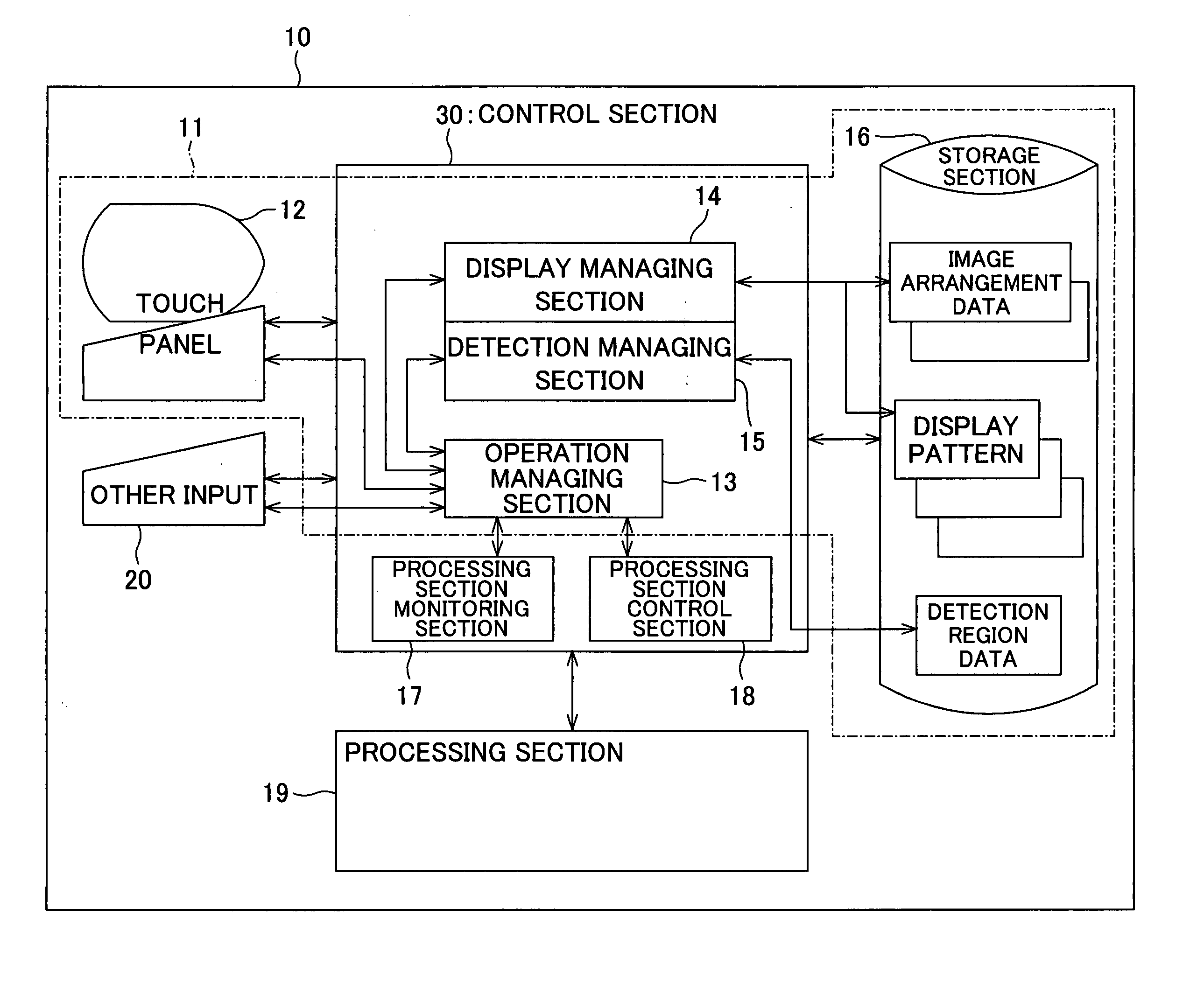
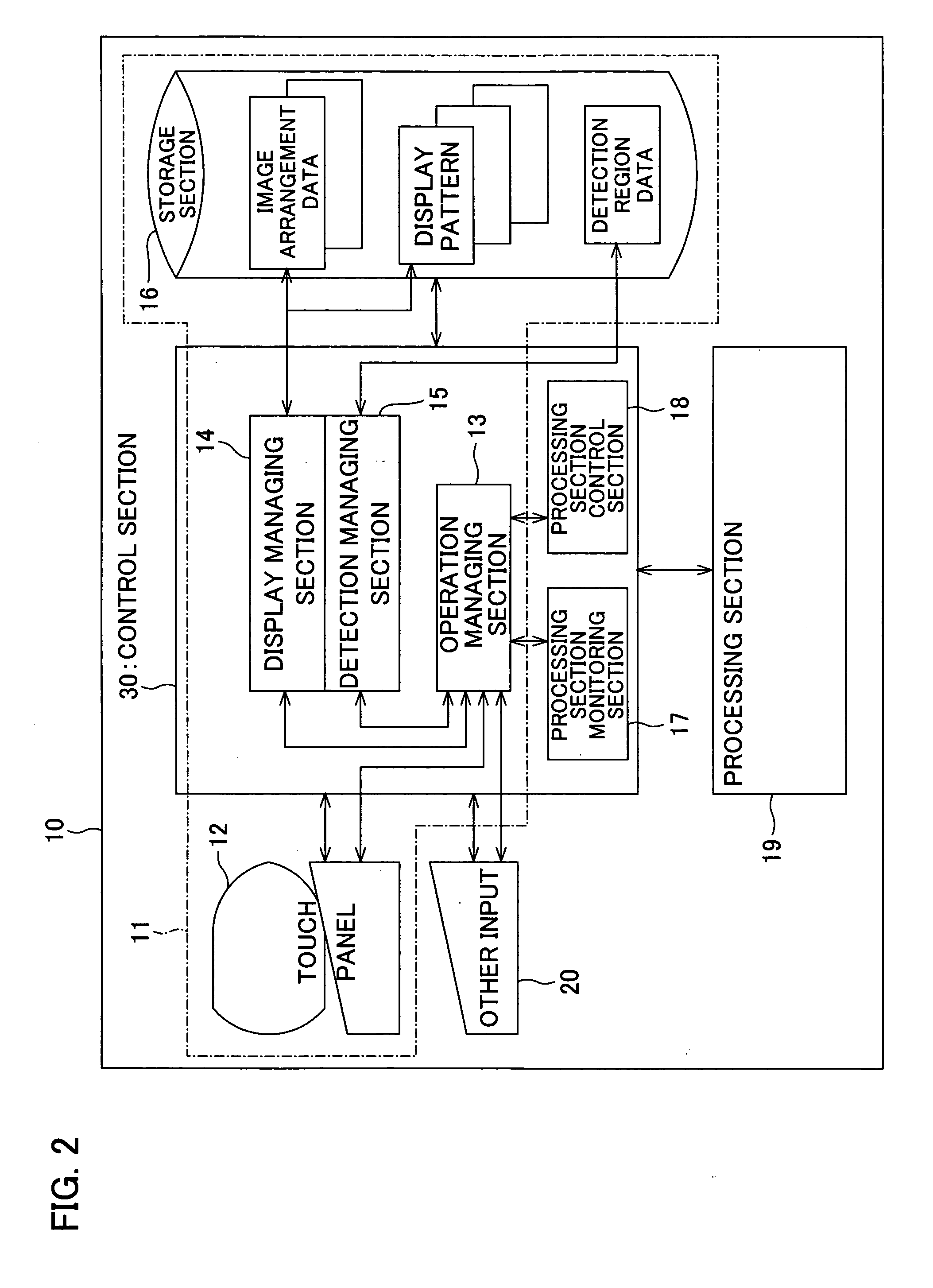
[0069]FIG. 2 is a block diagram illustrating respective structure examples of an image output device according to the present invention for carrying out image recording into a storage medium, and an information processing device provided in the image output device. For ease of explanation, the present embodiment uses the foregoing multifunctional device as the image output device.
[0070] First of all, the following explains the structure of an image processing device 11 provided in a multifunctional device 10. As shown in FIG. 2, the information processing device 11 includes a touch panel (display touch panel) 12 provided in an operation panel (not shown) of the multifunctional device 10. The touch panel 12 includes a display device such as a LCD (liquid crystal display), and a coordinates input device (tablet) for detecting a coordinates of a certain position specified by a command from a user, which command is made either by touching its screen or without touching the screen Those devices are combined together in the touch panel 12.
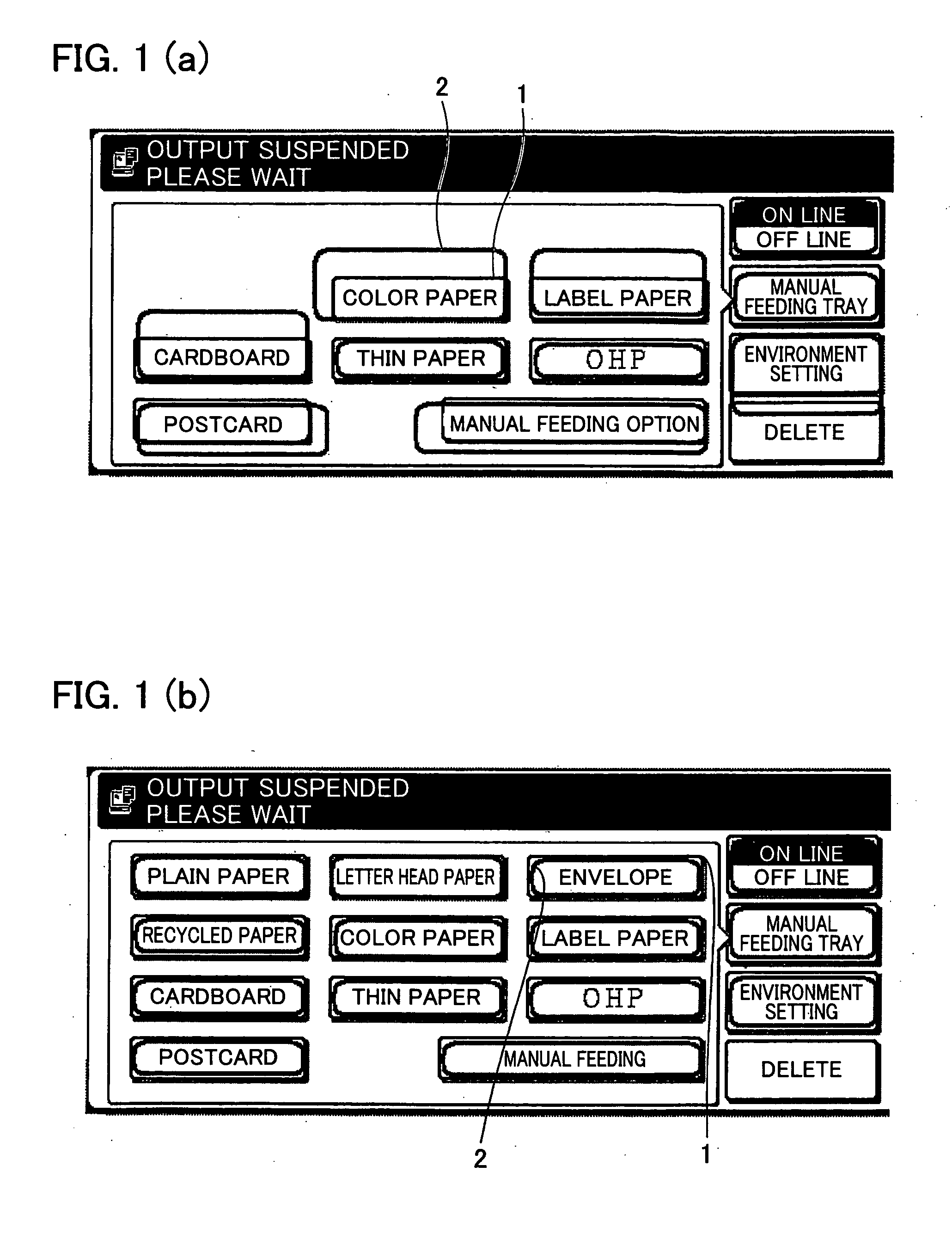
[0071] According to the circumstances, the touch panel displays on its screen an operation status of the multifunctional device 11, some information items regarding the device operation, various keys (button, icon etc.) for allowing users to input contact / non-contact commands. As mentioned above with FIG. 1(b), the keys are displayed with the outer frames, so that the keys are recognizable to the user. Meanwhile, the outer frame 1 indicates the key display region of the key. Each key has a corresponding detection region (inner frame 2) for the coordinates input device.
[0072] More specifically, the positional information indicating the key display region of a key on the screen is associated with the detection region data, which is positional information of the corresponding detection region that corresponds to the key.

Problems solved by technology

When such keys are displayed in large numbers on the display screen, different keys placed closer to one another increase the possibility that the touch panel could misidentify user's selection.
This arrangement makes it impossible to detect a light touch of the user's finger on the display area of the fare button, thus preventing an erroneous entry.
That is, a certain fare button is always placed at the same position on the screen and just switched back and forth between availability (valid) and unavailability (invalid) for display.
Therefore, a design of the pictograph cannot be changed according to a content of user selected operation.
That is, it is impossible to enhance operability by preventing erroneous detection in such a manner that a detection region of the available key is made larger so that detection is possible even with user's rough operation, when some keys become unavailable according to a content of the operation, and available keys are sparsely displayed on the screen, or conversely, the detection area is made smaller when the keys are densely displayed on the screen.

Method used


Image

  • Information processing method, information processing device, image output device, information processing program, and recording medium
  • Information processing method, information processing device, image output device, information processing program, and recording medium
  • Information processing method, information processing device, image output device, information processing program, and recording medium

Examples


first embodiment

[0069]FIG. 2 is a block diagram illustrating respective structure examples of an image output device according to the present invention for carrying out image recording into a storage medium, and an information processing device provided in the image output device. For ease of explanation, the present embodiment uses the foregoing multifunctional device as the image output device.

[0070] First of all, the following explains the structure of an image processing device 11 provided in a multifunctional device 10. As shown in FIG. 2, the information processing device 11 includes a touch panel (display touch panel) 12 provided in an operation panel (not shown) of the multifunctional device 10. The touch panel 12 includes a display device such as a LCD (liquid crystal display), and a coordinates input device (tablet) for detecting a coordinates of a certain position specified by a command from a user, which command is made either by touching its screen or without touching the screen Those...

operation example 1

[0100] According to the foregoing configuration, an operation of the information processing device 11 will be described through the case of the stationary arrangement in which the arrangement of displayed keys on the screen (for example, the number and order of displayed keys) is determined beforehand.

[0101] When the processing section 19 of the multifunction device 10 is in a certain state, the processing control section 18 sends a monitoring result concerning a state of the processing section 19 to the operation managing section 13. In response to the monitoring result, the operation managing section 13 grasps the operation status of the multifunction device 10.

[0102] When a user selects a certain position on the screen through the touch panel 12, the coordinates indicative of the selected position are input to the detection managing section 15 through the operation managing section 13. In response, the detection managing section 15 compares the coordinates with the coordinates ...

operation example 2

[0113] The following will discuss the operation of the information processing device 11, in a case where the key arrangement (such as the number and order of displayed keys) displayed on the screen is determined in advance and the keys are switched so as to be validated / invalidated.

[0114] Being similar to FIG. 3(a), FIG. 8 shows a standard state where the size of each button (A through I) is identical with the corresponding detection region, and all of the buttons A through I are valid.

[0115] Meanwhile, FIGS. 9(a)-9(f) illustrate respective cases where the detection region is altered at the time of invalidating one of the buttons A through E. More specifically, the figures show various patterns in a case where the detection region of a valid key is expanded over the key display region (cross-hatching part) of an invalid key.

[0116] The expansion of the detection region can be performed in all directions, e.g. in one direction lengthwise (FIGS. 9(a), 9(f)), in one direction crosswi...


PUM


Abstract

In case where a key having a detection region (inner frame) in which user's instructions can be accepted is displayed according to a certain operation status of an apparatus, and in case where there is an invalid region in which the user's instruction is not detectable is adjacent to a key display region (outer frame) of the key, the detection region of the key is caused to be larger than the key display region by utilizing the invalid region. Moreover, the detection region is expanded / shrunk according to key arrangement and a number of keys to be displayed. With this, the detection region of the key is expanded / shrunk according to according to the key arrangement on the screen in a display-cum-operation device in which a display device and a coordinate input device are integrated.

Description

[0001] This Nonprovisional application claims priority under 35 U.S.C. § 119(a) on Patent Application No. 2004 / 93193 filed in Japan on Mar. 26, 2004, the entire contents of which are hereby incorporated by reference. FIELD OF THE INVENTION [0002] The present invention relates to an information processing device which identifies a user's instruction by (i) display positions where keys (buttons, icons, or the like for user entry are displayed on a screen associated with the information processing device and (ii) a detection result of a position of the key selected by the user; more particularly, relates to an information processing device applicable to an display operation device, such as a display touch panel (i.e. a touch panel integrated with a display device), including a display screen, such as an LCD, and a touch panel superimposed thereon. BACKGROUND OF THE INVENTION [0003] In recent years, various information processing devices have been provided with a display section, such a...

Claims


Application Information

Patent Timeline
IPC IPC(8): G06F3/023H03M11/04G06F3/03G06F3/033G06F3/041G06F3/048G09G5/00H04N1/00
CPCG06F3/04886G06F3/04842G06F3/0237
Inventor KAWAKAMI, MASAAKIKUBO, HIROTSUGUSHIOZAKI, MASAKI
Owner SHARP KK
Learn More