Controlling system with fixed frequency driver for controlling an electrochromic element and method for the same

a control system and electrochromic element technology, applied in non-linear optics, instruments, optics, etc., can solve problems such as unreliability, complexity in design, and variable output duty cycle, and achieve cost savings for electrochromic elements, and reduce the complexity of the whole system

Inactive Publication Date: 2005-10-13
EXON SCIENCE INC
View PDF1 Cites 90 Cited by
  • Summary
  • Abstract
  • Description
  • Claims
  • Application Information

AI Technical Summary

Benefits of technology

[0006] It is a further object of the present invention to provide a controlling system and method for controlling an electrochromic element, which utilizes a simplified architecture to reduce complexity of the whole system for reaching both of a respond time and cost savings for electrochromic element.
[0007] It is a further object of the present invention to provide a controlling system and method for controlling an electrochromic element, which only utilizes a fixed frequency to drive the electrochromic element for reaching a better reliability than said variable duty cycle driver used in prior art.

Problems solved by technology

However, there are several problems in use of the variable output duty cycle for electrochromic element.
It is over complexity in design and therefore possibly makes unreliable.

Method used


Image

  • Controlling system with fixed frequency driver for controlling an electrochromic element and method for the same
  • Controlling system with fixed frequency driver for controlling an electrochromic element and method for the same
  • Controlling system with fixed frequency driver for controlling an electrochromic element and method for the same

Examples


Embodiment Construction

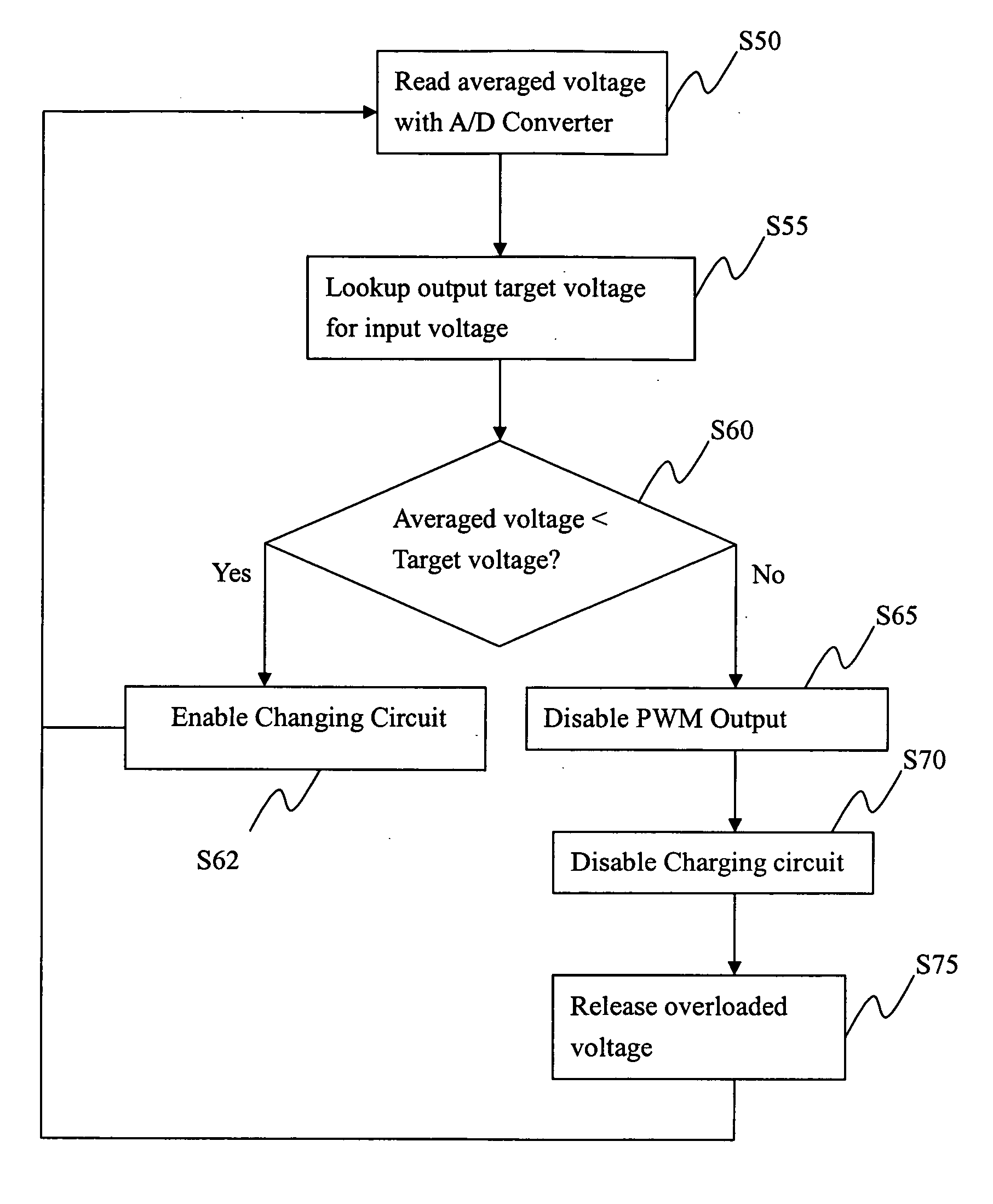
[0022] Differently from the prior art as mentioned above, the present invention relates to an controlling system for an electrochromic element driven by a pulse width modulated (PWM) signal which incorporates averaging of the modulated signal before the modulated signal is applied to the electrochromic element (hereinafter detailed).

[0023] Referring first to illustration in FIG. 3, the controlling system according to a preferred embodiment of the present invention, has a simplified architecture and therein includes a microcontroller 10, an amplifier 20, an analog-to-digital (A / D) converter 35, and a charging circuit 40.

[0024] Meanwhile, said microcontroller 10 is further provided with at least a programmable memory like ROM for pre-setting a look up table thereon, and a PWM unit for providing PWM function. The amplifier 20 is electrically coupled with a limited current circuit 25 for amplifying a PWM output signal with fixed frequency generated from PWM unit of the microcontroller...


PUM

PropertyMeasurementUnit
reflectanceaaaaaaaaaa
frequencyaaaaaaaaaa
output voltageaaaaaaaaaa

Abstract

A controlling system and method for controlling an electrochromic element, utilizes a simplified architecture, including at least a microcontroller, a A / D converter and a charging circuit, to reduce complexity of the whole system for reaching both of a respond time and cost savings for the electrochromic element. And the controlling system and method only utilizes a fixed frequency to drive the electrochromic element for reaching a better reliability than a variable duty cycle driver used in prior art.

Description

BACKGROUND OF THE INVENTION [0001] 1. Field of the Invention [0002] The present invention relates to a controlling system and method for controlling an electrochromic element, and more particularly in to a controlling system and method using a fixed frequency for driving a reflectance of an electrochromic element. [0003] 2. Description of the Prior Art [0004] As known, various electrochromic elements, i.e. electrochromic mirror and window systems applied in automotive applications, are being widely used. Relatively, several apparatus for controlling the reflectance of said electrochromic elements are progressively developed. For example, U.S. Pat. No. 6,084,700 as illustrated in FIGS. 1 and 2, discloses that an electrical circuit utilizes active loading or voltage feedback of electrochromic element to control a reflectance of an electrochromic element. The electrical circuit provided a programmable microcontroller is capable of generating a variable duty cycle driver to adjust the c...

Claims


Application Information

Patent Timeline
Patent Type & Authority Applications(United States)
IPC IPC(8): G02F1/15G02F1/153G02F1/163
CPCG02F1/163
Inventor HUANG, TAI-HSIUNGHSIAO, SHUN-HSIANGSU, WEN-WEICHEN, KUEI-HUNG
Owner EXON SCIENCE INC
Why Eureka
Try Eureka