Dual mode mirror imaging system

Inactive Publication Date: 2005-10-13
ARMY DEPT OF UNITED STATES OF AMERICA AS REPRESENTED BY THE
View PDF7 Cites 22 Cited by
  • Summary
  • Abstract
  • Description
  • Claims
  • Application Information

AI Technical Summary

Benefits of technology

[0006] It is therefore an object of this invention to image at both mid-wave infrared wave

Problems solved by technology

Multi-spectral designs are often limited to all reflective designs because of axial chromatic aberration.
All-reflective designs may contain off-axis mirrors,

Method used


Image

  • Dual mode mirror imaging system
  • Dual mode mirror imaging system
  • Dual mode mirror imaging system

Examples


Embodiment Construction

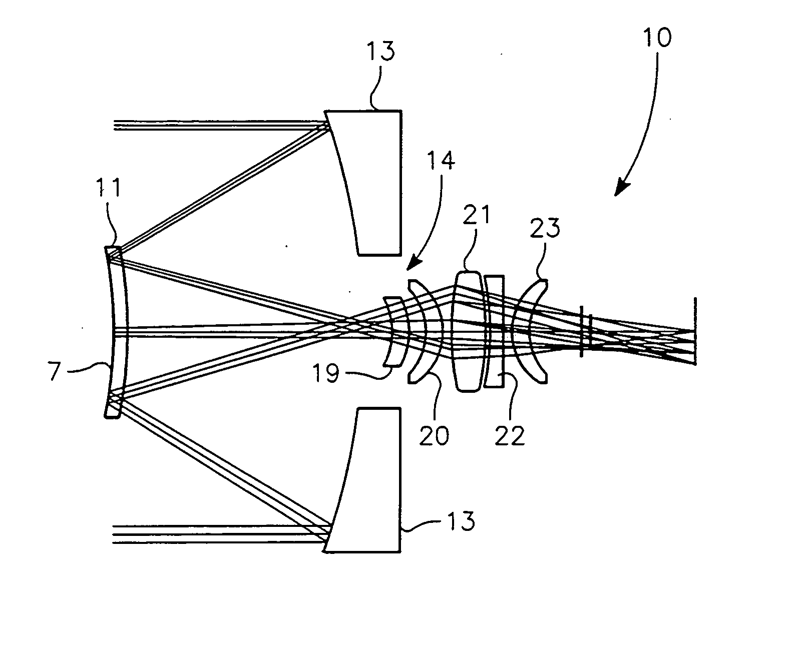
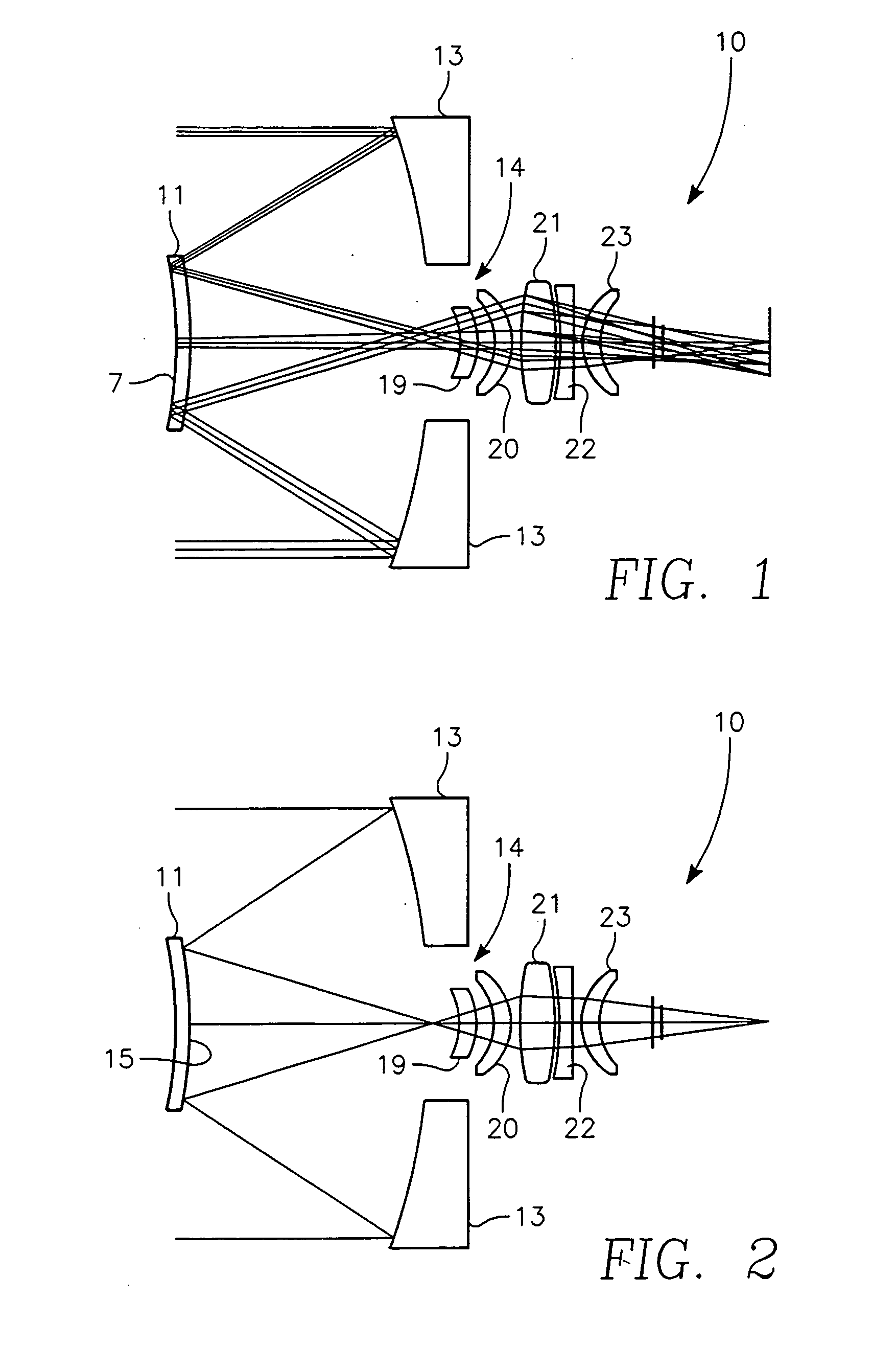
[0016] Referring to the Figures, wherein like reference numerals designate like or corresponding parts, an embodiment of the dual mode mirror imaging system 10 is illustrated in FIG. 1 and FIG. 2. FIG. 1 shows the action of the imaging system for the 3.9 to 5.0 micron mid-wave infrared band wavelengths, and FIG. 2 shows the action of the imaging system for the 1.06 micron laser. A two mirror Cassegrain type objective assembly is used, utilizing two aspheric mirrors. The primary mirror 13 is an aluminum mirror with a hole 14 removed from its center for the imager optics. The secondary mirror 11 is a convex Mangin mirror made out of germanium. The primary and secondary mirror interact to provide an infrared imaging system with laser see spot capability as more fully described hereinafter.

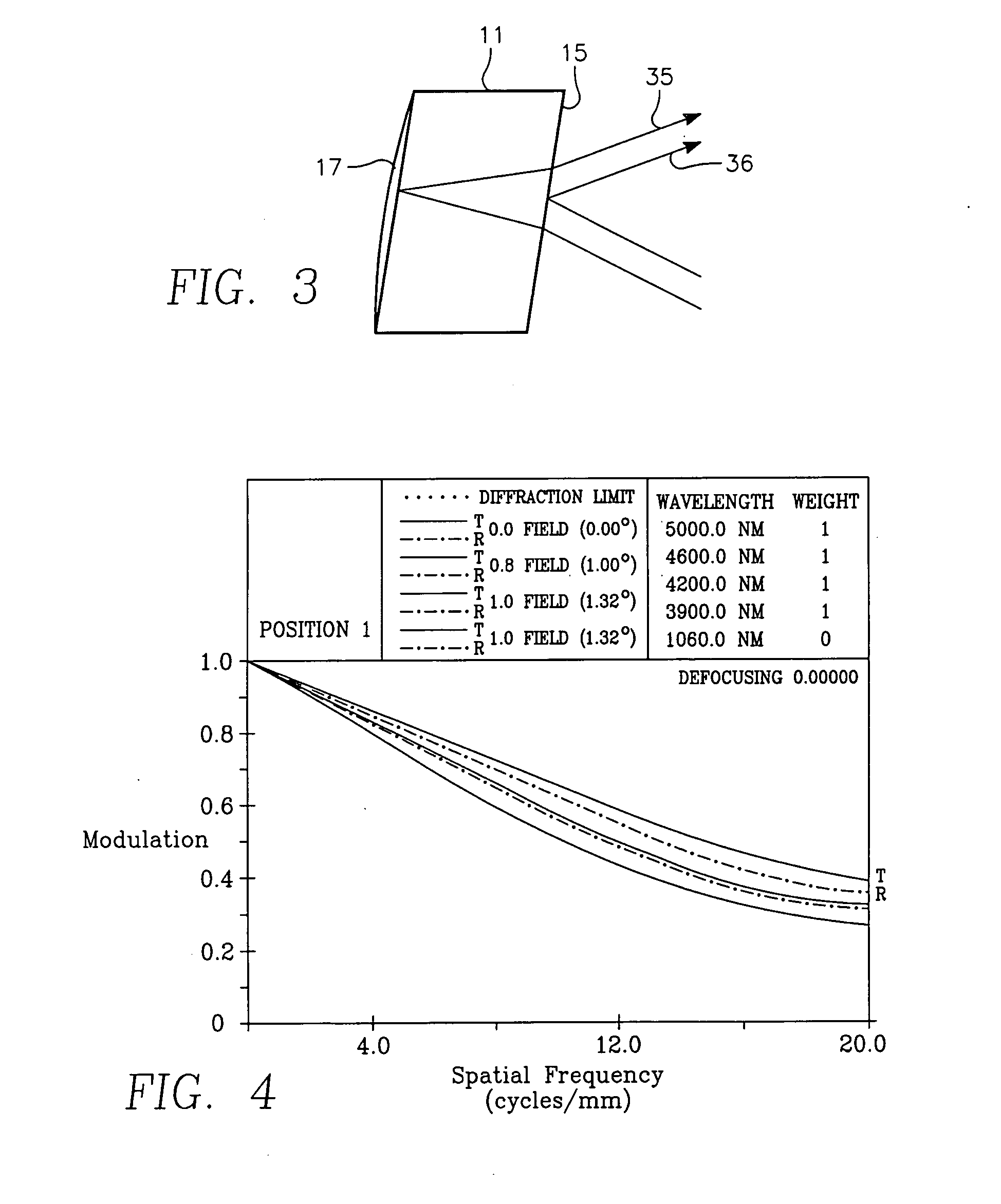
[0017]FIG. 3 illustrates the action of the dual mode mirror 11 that enables this system to image a 1.06 micron laser and wavelengths in the 3.9 to 5.0 micron infrared band. Referriing now primarily t...


PUM


Abstract

A dual mode mirror imaging system comprising a Cassegrain-type objective assembly having a primary mirror with a hole in its center and a secondary mirror spaced in front of the primary mirror, and imager optics disposed in the hole. The secondary mirror is adapted to receive laser wavelength light and infrared wavelength light reflected from the primary mirror and to reflect the light back through the imager optics to a focal plane. The secondary mirror has one reflecting surface for the laser light and another reflecting surface for the infrared light. The pair of reflecting surfaces is positioned to change the optical path length between the laser light and the infrared light so that the laser light and the infrared light are imaged at the same focal plane without defocusing.

Description

GOVERNMENT INTEREST [0001] The invention described herein may be manufactured, used, sold, imported, and / or licensed by or for the Government of the United States of America.BACKGROUND OF THE INVENTION [0002] This invention relates in general to optical devices, and more particularly, to optical imaging systems. [0003] The use of multi-spectral systems is becoming more common with the development of new focal plane arrays. [0004] One such application is the ability to see the laser spot of a laser while imaging in the mid-wave infrared band. This “see-spot” capability is extremely useful for bore-sighting a laser to an imaging system. By enabling the “see-spot” in the infrared, bore-sighting is possible both at night and during the day. [0005] Multi-spectral designs are often limited to all reflective designs because of axial chromatic aberration. All-reflective designs may contain off-axis mirrors, taking up a large volume and providing difficult tolerances. This would make it extr...

Claims


Application Information

Patent Timeline
IPC IPC(8): G02B17/00G02B17/06G02B17/08
CPCG02B17/0694G02B17/0808G02B17/0896G02B17/0856G02B17/0852
Inventor VIZGAITIS, JAY N.
Owner ARMY DEPT OF UNITED STATES OF AMERICA AS REPRESENTED BY THE
Why Eureka
Try Eureka