Stationary Tomographic Mammography System

a tomographic and mammography technology, applied in the field of x-ray imaging machines, can solve the problems of image motion artifacts, patient may sustain extended compression times, and necessitate acceleration and deceleration of angular movement, so as to eliminate mechanically induced artifacts and eliminate shock and vibration translation

Active Publication Date: 2005-10-13
GENERAL ELECTRIC CO
View PDF15 Cites 38 Cited by
  • Summary
  • Abstract
  • Description
  • Claims
  • Application Information

AI Technical Summary

Benefits of technology

[0013] One advantage of the present invention is that motion free tomographic or multi-projection imaging eliminates mechanically induced artifacts in the sensitive detection system.
[0014] Another advantage of the present invention is that this type of system eliminates the shock and vibration translated from the mount to detector during the detector read, which may be conducted during mount movement.
[0015] Other advantages of the present invention will become apparent upon reading the following detailed description and appended claims and upon reference to the accompanying drawings.

Problems solved by technology

However, the mechanical motion required to move the X-ray source may induce image motion artifacts and may also require sub-optimal trade-offs between X-ray source arm acceleration mechanics and overall system ergonomics.
In contrast, if the X-ray source is manually moved to each projection angle, the patient may sustain extended compression times, which may be undesireable.
In addition, certain rapid multi-view applications may require that the X-ray source be completely stationary during the actual exposure thereby necessitating acceleration and deceleration of the angular movement.
Because very sensitive flat panel X-detectors are often utilized in such systems, it is also known that even moderate levels of shock and vibration applied to their panel read-out interconnection systems may cause image artifacts to be generated.
The disadvantages associated with current imaging systems have made it apparent that a new technique for mammographic imaging is needed.

Method used


Image

  • Stationary Tomographic Mammography System
  • Stationary Tomographic Mammography System

Examples


Embodiment Construction

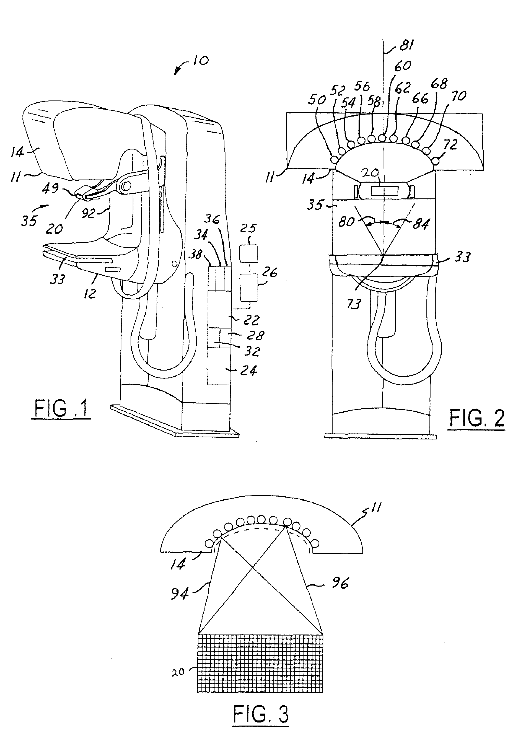
[0020] The present invention is illustrated with respect to a scanning system 10 particularly suited to the medical field.

[0021] The present invention is, however, applicable to various other scanning systems utilized in a variety of other environments, as will be understood by one skilled in the art.

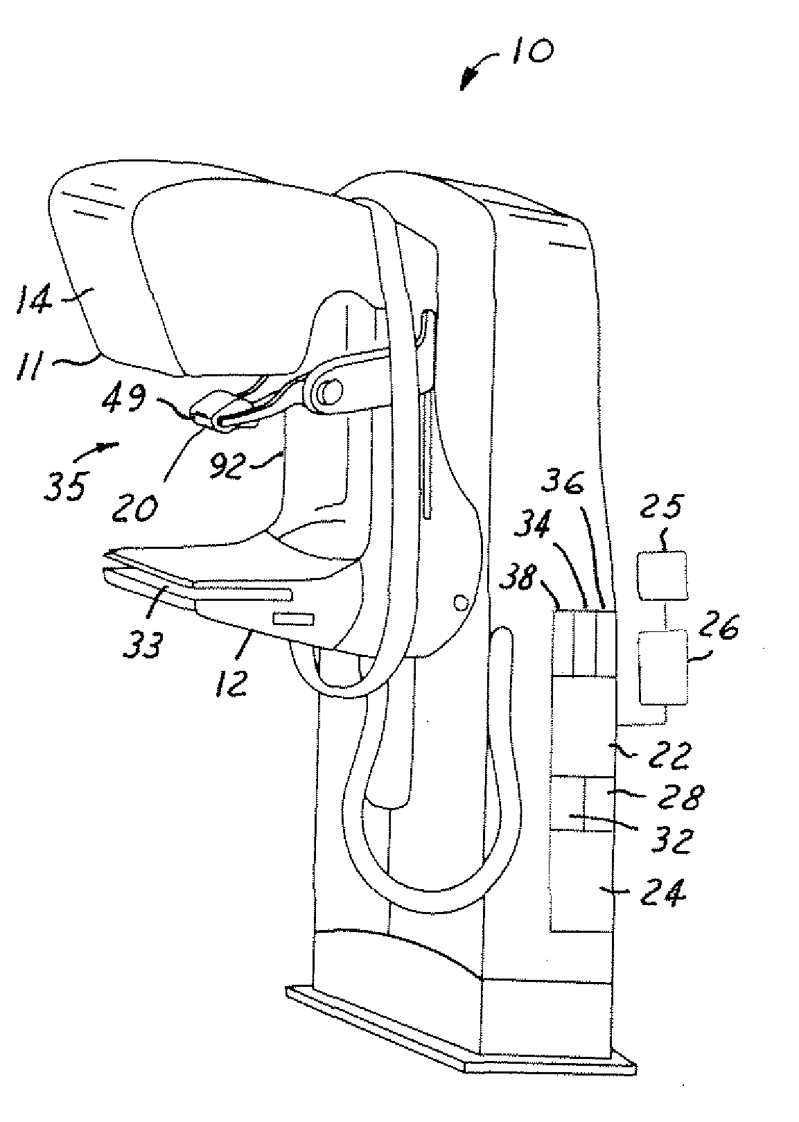
[0022] Referring to FIGS. 1 and 2, a scanning system 10 including a support system 11 coupled to a mount 12, in accordance with one embodiment of the present invention, is illustrated. Coupled to the support system 11 is a plurality of stationary X-ray sources 14 generating X-ray fluxes, which pass through an object (e.g. a patient). Also coupled to the mount 12 is an X-ray detector 20, which generates a detector signal in response to the X-ray fluxes.

[0023] The system 10 further includes a control unit 22, coupled to a host computer 24 and display 26 and various other widely known control and display components, receiving the detector signal and responding by generating an image sig...


PUM

PropertyMeasurementUnit
projection anglesaaaaaaaaaa
angleaaaaaaaaaa
holding areaaaaaaaaaaa

Abstract

A mammography scanning system having a detector includes an arc-shaped support system having a number of X-ray emitters coupled thereto. The X-ray emitters generate a plurality of X-ray fluxes towards a common focus at varying angles with respect to the focus. Also, each of the X-ray emitters is collimated to view an entire detector field of view.

Description

BACKGROUND OF INVENTION [0001] The present invention relates generally to X-ray imaging machines, and particularly to a stationary tomographic mammography system. [0002] A traditional X-ray imaging system includes an X-ray source and a detector array for generating an internal image of an object. As is well known, the X-ray source generates X-rays, which are attenuated by the object (i.e. they either pass through the object or are absorbed therein). [0003] As a result, the transmitted X-rays vary in intensity. The detector array receives and measures the resultant X-ray flux so as to generate electrical signals necessary for constructing an internal image of the object. [0004] In at least one known mammography imaging system, an X-ray source projects a fan-shaped beam, which is collimated to lie within an X-Y plane of a Cartesian coordinate system and is generally referred to as the “imaging plane.” The X-ray beam passes through the object being imaged, such as a patient's breast. T...

Claims


Application Information

Patent Timeline
Patent Type & Authority Applications(United States)
IPC IPC(8): A61B6/00A61B6/03A61B6/04G01N23/06H05G1/42
CPCA61B6/025A61B6/502A61B6/4488A61B6/4007
Inventor KAUTZER, JEFFREY ALANUNGER, CHRISTOPHER DAVID
Owner GENERAL ELECTRIC CO
Why Eureka
Try Eureka