Suction inserter

a technology of suction inserter and inserter, which is applied in the field of surgical instruments, can solve the problems of obscuring the surgeon's vision, complicated positioning of the cup, and many of the same difficulties of the liner, and achieve the effect of improving viewing

Inactive Publication Date: 2005-10-13
DEPUY SYNTHES PROD INC
View PDF38 Cites 48 Cited by
  • Summary
  • Abstract
  • Description
  • Claims
  • Application Information

AI Technical Summary

Benefits of technology

[0012] In one embodiment of the invention, a suction inserter comprises a shaft with an internal channel sealing connected to a bulb syringe at one end portion and a head at the second end portion. The head is configured to sealingly fit within an acetabular liner. The shaft is bent between the first end portion and the second end portion to allow improved viewing when inserting an acetabular liner.

Problems solved by technology

The positioning of the cup is complicated by the fact that incisions used in hip or femoral operations may be quite deep, with the implantation site remote from the initial incision location.
The implantation of a liner presents many of the same difficulties as the implantation of the cup.
The instruments used to keep the incision site open crowd the incision area and obscure the surgeon's vision.
Obviously, obscuring the vision of the surgeon hinders the procedure and can result in undesired delays.
Moreover, because the instrument must extend beyond the rim of the acetabular liner in order to properly engage the acetabular cup, a surgeon's view of the implantation site may be negatively impacted.
Additionally, the release mechanism is typically located such that a surgeon's hand must be placed over the incision site, further obscuring the surgeon's vision.
Additionally, the connection of suction tubing to the device hinders the maneuverability of the device.
Moreover, the tubing creates an obstacle for medical personnel that may hinder movement in and around the device.
Thus, placement of acetabular liners requires much lower levels of vacuum than the vacuum associated with the above vacuum based device.
Unfortunately, such a device has limited usefulness.
Many acetabular liners are now made of ceramic and other heavy materials, and the limited vacuum available with the suction cup device is insufficient to provide a secure grasp of the acetabular liner.
Moreover, once the acetabular liner is installed, there is no easy way to release the suction cup.

Method used


Image

  • Suction inserter
  • Suction inserter
  • Suction inserter

Examples


Embodiment Construction

[0032] For the purposes of promoting an understanding of the principles of the invention, reference will now be made to the embodiments illustrated in the drawings and described in the following written description. It is understood that no limitation to the scope of the invention is thereby intended. It is further understood that the present invention includes any alterations and modifications to the illustrated embodiments and includes further applications of the principles of the invention as would normally occur to one skilled in the art to which this invention pertains.

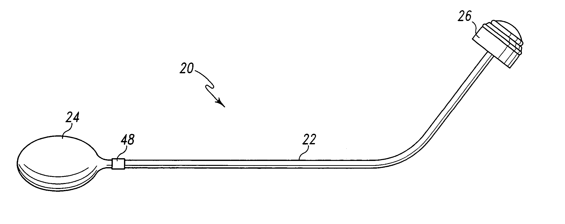
[0033] Referring generally to FIG. 5, a suction inserter for insertion of an acetabular liner into an acetabular cup is shown, hereinafter generally designated by reference numeral 20. Suction inserter 20 comprises bent shaft 22, bulb syringe 24, and head 26. Head 26 comprises o-ring 28 and o-ring 30 as shown in FIG. 6. FIG. 7, which is cross sectional view of head 26 taken along line A-A of FIG. 6, shows o-ring...


PUM


Abstract

A hand held instrument for inserting an acetabular liner into acetabular cup is provided. The instrument includes a bulb syringe, a shaft and a head configured to sealingly engage an acetabular liner to create a sealed area between the acetabular liner and the head. The bulb syringe is used to create a vacuum in the sealed area and/or to force air into the sealed area. After the acetabular liner is placed into an acetabular cup, the vacuum is released and/or air is forced into the sealed area to force the acetabular liner off of the head.

Description

FIELD OF THE INVENTION [0001] The present invention relates to surgical instruments, and particularly to an instrument for positioning an acetabular insert. BACKGROUND OF THE INVENTION [0002] Joint arthroplasty is a well known surgical procedure by which a diseased and / or damaged natural joint is replaced by a prosthetic joint. Joint arthroplasty is commonly performed for hips, knees, elbows, and other joints. The health and condition of the joint to be replaced dictate the type(s) of prosthesis necessary to replace the natural joint. Prosthetic components that are used in a hip arthroplasty include acetabular cups and acetabular liners. FIG. 1 shows acetabular cup 10 and acetabular liner 12. An acetabular cup is implanted in the acetabular cavity in the pelvis to replace the natural acetabulum. The acetabulum receives the head or ball of a femoral component. FIG. 2 depicts the left hip of an individual, showing the general location of the pelvis 14 and femur 16. Replacement of the ...

Claims


Application Information

Patent Timeline
Patent Type & Authority Applications(United States)
IPC IPC(8): A61B17/58A61F2/00A61F2/30A61F2/34A61F2/46
CPCA61F2/34A61F2/4609A61F2002/30235A61F2230/0069A61F2002/30584A61F2002/4685A61F2220/0025A61F2002/30405
Inventor BIHARY, DIANESIEBENECK, ANTHONY CHARLESGOLDSTEIN, WAYNE M.
Owner DEPUY SYNTHES PROD INC
Why Eureka
Try Eureka