Fingerprint sensors using membrane switch arrays

Inactive Publication Date: 2005-10-20
LENOVO PC INT
View PDF52 Cites 18 Cited by
  • Summary
  • Abstract
  • Description
  • Claims
  • Application Information

AI Technical Summary

Problems solved by technology

Disposing a protrusion of the texture over the membrane switch causes a flexure of the membrane resulting in a change in contact state between the fixed electrode and the movable electrode.

Method used


Image

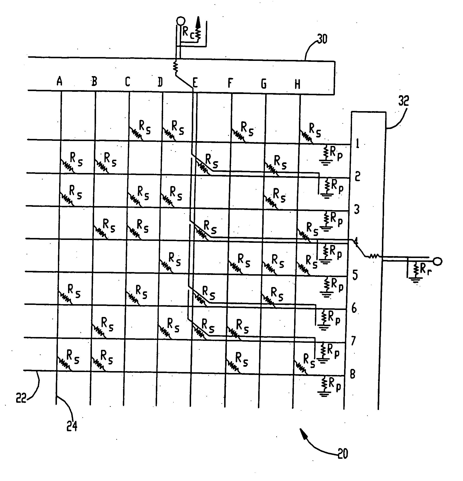
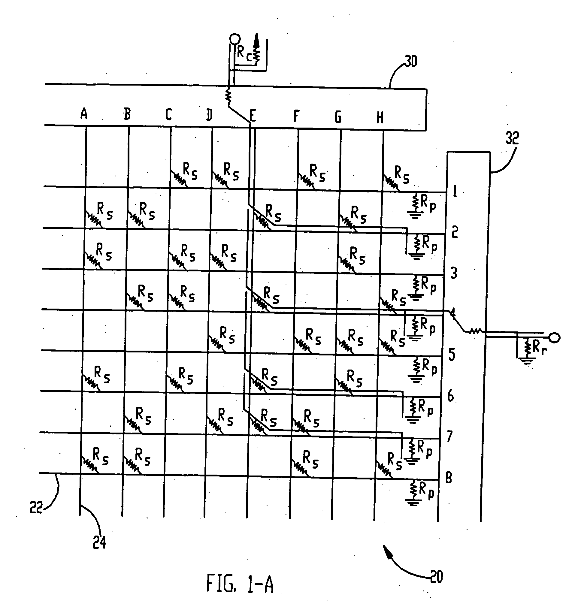
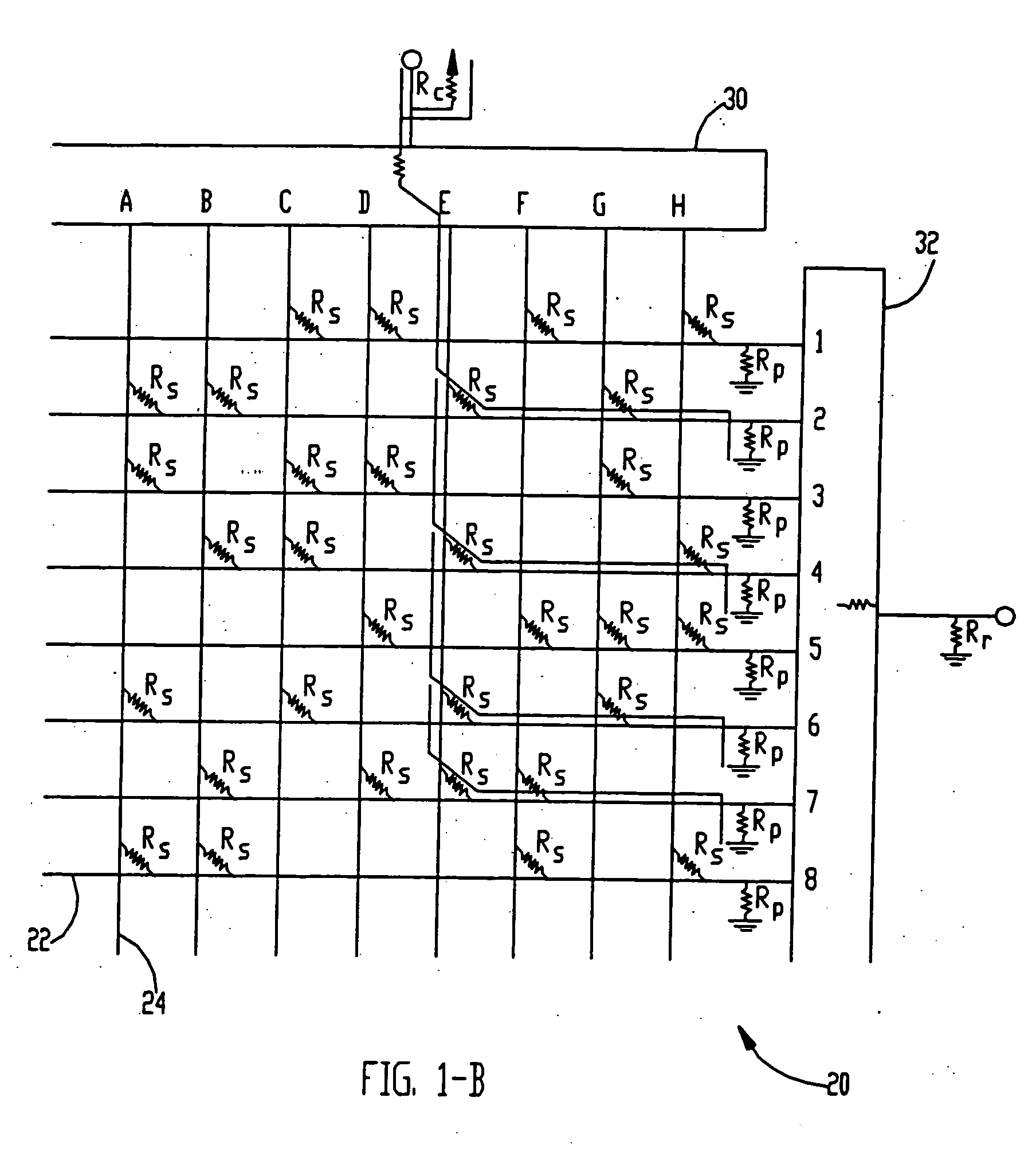
  • Fingerprint sensors using membrane switch arrays
  • Fingerprint sensors using membrane switch arrays
  • Fingerprint sensors using membrane switch arrays

Examples


Embodiment Construction

[0017] In the following description, it is understood that each recited element or structure can be formed by or be part of a monolithic structure, or be formed from multiple distinct structures. Unless otherwise specifically stated, the statement that a first layer or structure is disposed or deposited on a second layer or structure is understood to allow for the presence of parts of the first or second layer or structure that are not so disposed or deposited, and further allow for the presence of intermediate layers or structures between the first and second layers or structures. The terms “chip base” and “chip substrate” are understood to encompass monolithic substrates as well as structures containing multiple layers or parts. The terms “upper” and “lower” are used to describe relative positions, and do not necessarily refer to the direction of gravity during operation of the sensor. A set of elements is understood to include one or more elements. A plurality of elements is unde...


PUM

PropertyMeasurementUnit
resistanceaaaaaaaaaa
heightaaaaaaaaaa

Abstract

A method of making an integrated texture sensor for sensing a texture is described. In one embodiment, the method is directed to a sensor that that is protected from external contaminating particulates and will self-equalize using air from outside the sensor. Further combinations of such protection among various membrane switches, in combination with various types of membranes, is described. In another embodiment, a method of making a skin-texture sensor for sensing a skin texture having a plurality of ridges and a plurality of valleys is described, such that when completed, applying a ridge of the texture to a membrane switch will cause flexure of the membrane resulting in a contact between the lower electrode and the upper electrode, the contact establishing an electrical communication between said one of the row lines and said one of the column lines, whereas disposing a valley of the texture over said each membrane switch will not result in the contact between the lower electrode and the upper electrode.

Description

RELATED APPLICATION DATA [0001] This application is a divisional of U.S. patent application Ser. No. 10 / 038,505 filed Dec. 20, 2001, which is a continuation-in-part of U.S. patent application Ser. No. 09 / 571,765, filed May 16, 2000, now U.S. Pat. No. 6,578, 436, which are incorporated by reference herein.FIELD OF THE INVENTION [0002] The invention relates to biometric identification systems and methods, and in particular to fingerprint or skin texture identification systems and methods using switch arrays. BACKGROUND OF THE INVENTION [0003] The fingerprint sensing industry uses several different conventional technologies to capture images of an individual's fingerprints. Two prominent technologies are optical-based sensors and capacitance-based sensors. In a typical optical sensor, a light source, lenses and a prism are used to image the ridges and valleys on a fingerprint, based on differences in the reflected light from the features. Conventional capacitance sensors include two-di...

Claims


Application Information

Patent Timeline
Patent Type & Authority Applications(United States)
IPC IPC(8): G01R27/08G06K9/00H01H1/00H01H59/00H01H67/22
CPCG06K9/0002G06K9/00053Y10T29/49004H01H67/22H01H1/0036G06V40/1329G06V40/1306
Inventor DECONDE, KEITH T.GANAPATHI, SRINIVASAN K.GLUCK, RANDOLPH S.HOVEY, STEVE H.PRAKASH, SHIVASTOESSEL, CHRISTIAN
Owner LENOVO PC INT
Why Eureka
Try Eureka