Method of forming circuit assembly

Inactive Publication Date: 2005-10-20
CREDIT SUISSE SYDNEY BRANCH
View PDF20 Cites 30 Cited by
  • Summary
  • Abstract
  • Description
  • Claims
  • Application Information

AI Technical Summary

Benefits of technology

[0008] The present invention is directed to a method of forming a circuit assembly, such as including a radio frequency identification device (RFID), wherein first and second portions of an antenna of the circuit assembly are provided on respective first and second substrates, with the associated electrical circuit, having first and second electrical contacts on respective opposite sides t

Problems solved by technology

As will be appreciated, the need to precisely relatively position such components detra

Method used


Image

  • Method of forming circuit assembly
  • Method of forming circuit assembly
  • Method of forming circuit assembly

Examples


Example

[0025] While the present invention is susceptible of embodiment in various forms, there is shown in the drawings, and will hereinafter be described, presently preferred embodiments, with the understanding that the present disclosure is to be considered as an exemplification of the invention, and is not intended to limit the invention to the specific embodiment illustrated.

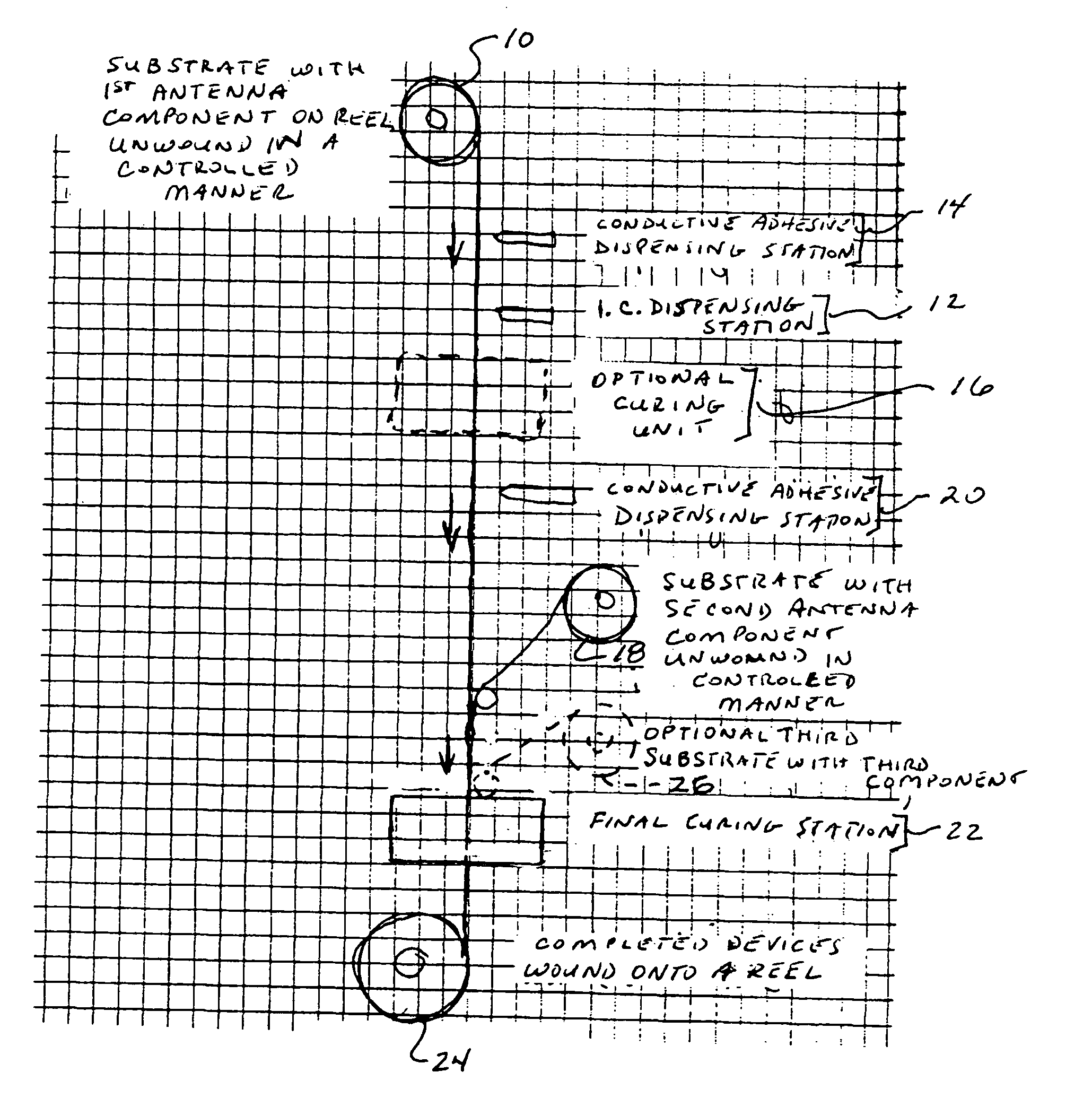
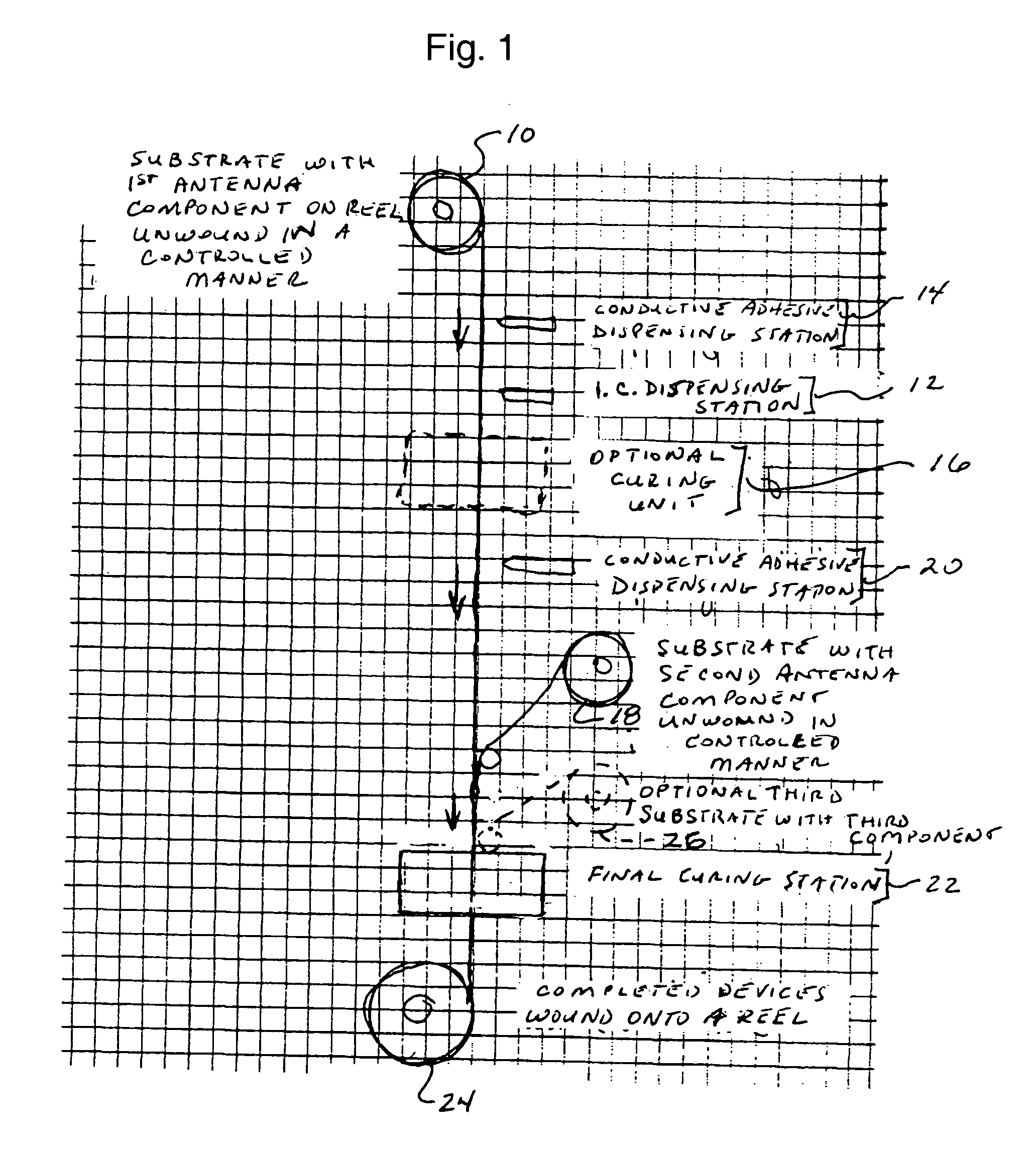
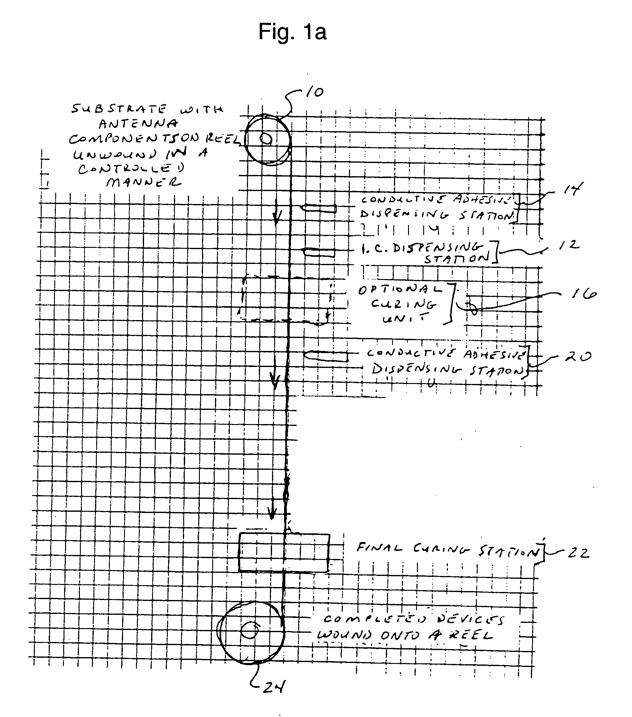
[0026] The present invention is directed to a method for manufacturing a circuit assembly, such as including an integrated circuit and an antenna, using an integrated circuit that permits a single connection to be formed on each of top and bottom surfaces of the circuit, rather than with both connections on a single side of the circuit. The present invention may advantageously be employed for manufacture of a circuit assembly including a radio frequency identification device (RFID), with low-cost manufacturing of such an assembly permitted by the present invention facilitating cost-effective, widespread use of suc...


PUM


Abstract

The present invention is directed to a method of forming a circuit assembly, such as including a radio frequency identification device (RFID), wherein first and second portions of an antenna of the circuit assembly are provided on respective first and second substrates, with the associated electrical circuit, having first and second electrical contacts on respective opposite sides thereof, positioned between the first and second substrates. Alternatively, first and second portions of an antenna of the circuit assembly are provided on a substrate, with the associated electrical circuit, having first and second electrical contacts on respective opposite sides thereof, electrically joined to the respective antenna portions. Highly efficient manufacture is thus promoted.

Description

CROSS REFERENCE TO RELATED APPLICATIONS [0001] This application claims the benefit of U.S. Provisional Application Ser. No. 60 / 563,714 filed on Apr. 20, 2004, and U.S. Provisional Application Ser. No. 60 / 571,255 filed on May 14, 2004, the disclosures of which are fully incorporated by reference herein.TECHNICAL FIELD [0002] The present invention relates generally to a method of forming a circuit assembly, such as including a radio frequency identification device (RFID), and more particularly to a method of forming a circuit assembly including an antenna, wherein first and second portions of the antenna are either (1) formed on respective substrates between which the associated circuit is positioned; or (2) formed on substrate, with the associated circuit having electrical connectors on opposite sides thereof respectively electrically joined to the antenna positions. BACKGROUND OF THE INVENTION [0003] Use of various types of electrical circuits, including radio frequency identificati...

Claims


Application Information

Patent Timeline
IPC IPC(8): G06K19/077G08B13/14
CPCG06K19/07718G06K19/07749G06K19/0775G08B13/244G06K19/07783G06K19/07784G06K19/07779G06K19/077G06K19/07H01L21/02
Inventor ROWE, HARRY B. JR.
Owner CREDIT SUISSE SYDNEY BRANCH
Why Eureka
Try Eureka