Bridging member for electrical terminals

a cross-bridging member and electrical terminal technology, applied in the manufacture of contact member cases/bases, coupling device connections, electrical apparatus, etc., can solve the problems of small elastic deformation properties, and achieve the effect of improving creep and air gaps and high current intensities

Active Publication Date: 2005-10-20
WAGO VERW GMBH
View PDF10 Cites 22 Cited by
  • Summary
  • Abstract
  • Description
  • Claims
  • Application Information

AI Technical Summary

Benefits of technology

[0012] Another advantage of the invention is produced from the free space, which is formed inside the sleeve of insulating material that surrounds each connecting pin, between the sleeve of insulating material and the metal of the connecting pin, whereby in an advantageous manner, the open end of the sleeve of insulating material can be guided up to the vicinity of the current-bus connector receptacle of the respective terminal when the bridging member is plugged in.
[0013] The creep and air gaps between adjacent bridging-member connecting pins conducting different electrical potentials are considerably improved by this measure. This neighboring situation of differing electrical potentials is often encountered between the connecting pin of one bridging member on the end side and the end-side connecting pin of an adjacent plugged-in bridging member in row arrangements of terminals, when the two bridging members conduct different electrical potentials.
[0014] Another essential advantage of a bridging member according to the invention concerns its applicability to provide bridging members with gaps in row arrangements of terminals. To produce gaps, as is known, one or more connecting pins is removed from the bridging comb of a bridging member. In the case of a bridging member according to the invention, this gap is produced by grasping with tweezers the outer free end of a connecting pin, which projects out of the sleeve of insulating material that surrounds the connecting pin and removing the pin by vigorous rotating movements of the connecting pin around its material constriction (=a material weak spot, which serves in this case as a break-off site). Then the empty sleeve of insulating material remains in its entire depth or in its entire length, preferably if the material constriction is positioned in the depth of the sleeve of insulating material in the vicinity of the bridge head of the bridging member.
[0015] If the entire depth of the empty sleeve of insulating material remains, this will considerably improve the creep and air gaps between the skipped-over current bus of a terminal and the bridge head of the bridging member in the region where the gap is bridged, so that gap bridgings are possible with high current intensities.DETAILED

Problems solved by technology

This is true even when the bridging member is manufactured as a low-cost, punched-out part and its material in fact possesses good electrical conductivity, but has only small elastic deformation properties.

Method used


Image

  • Bridging member for electrical terminals
  • Bridging member for electrical terminals

Examples


Embodiment Construction

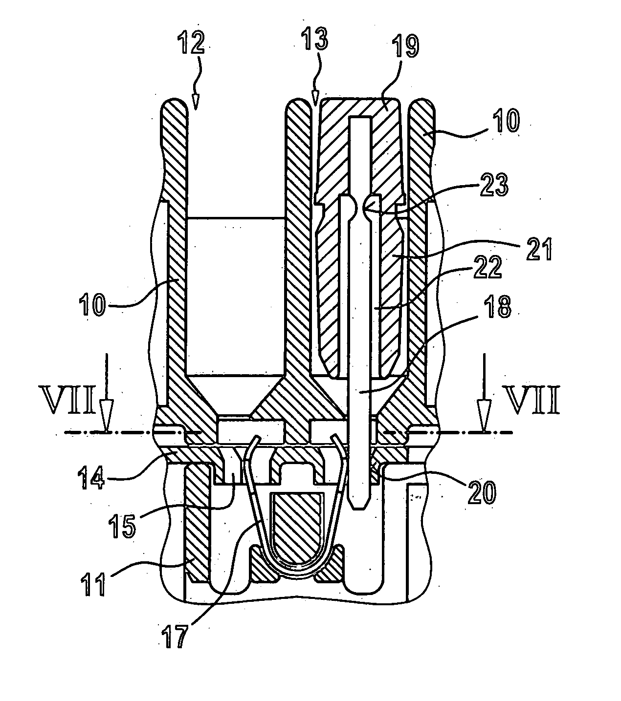
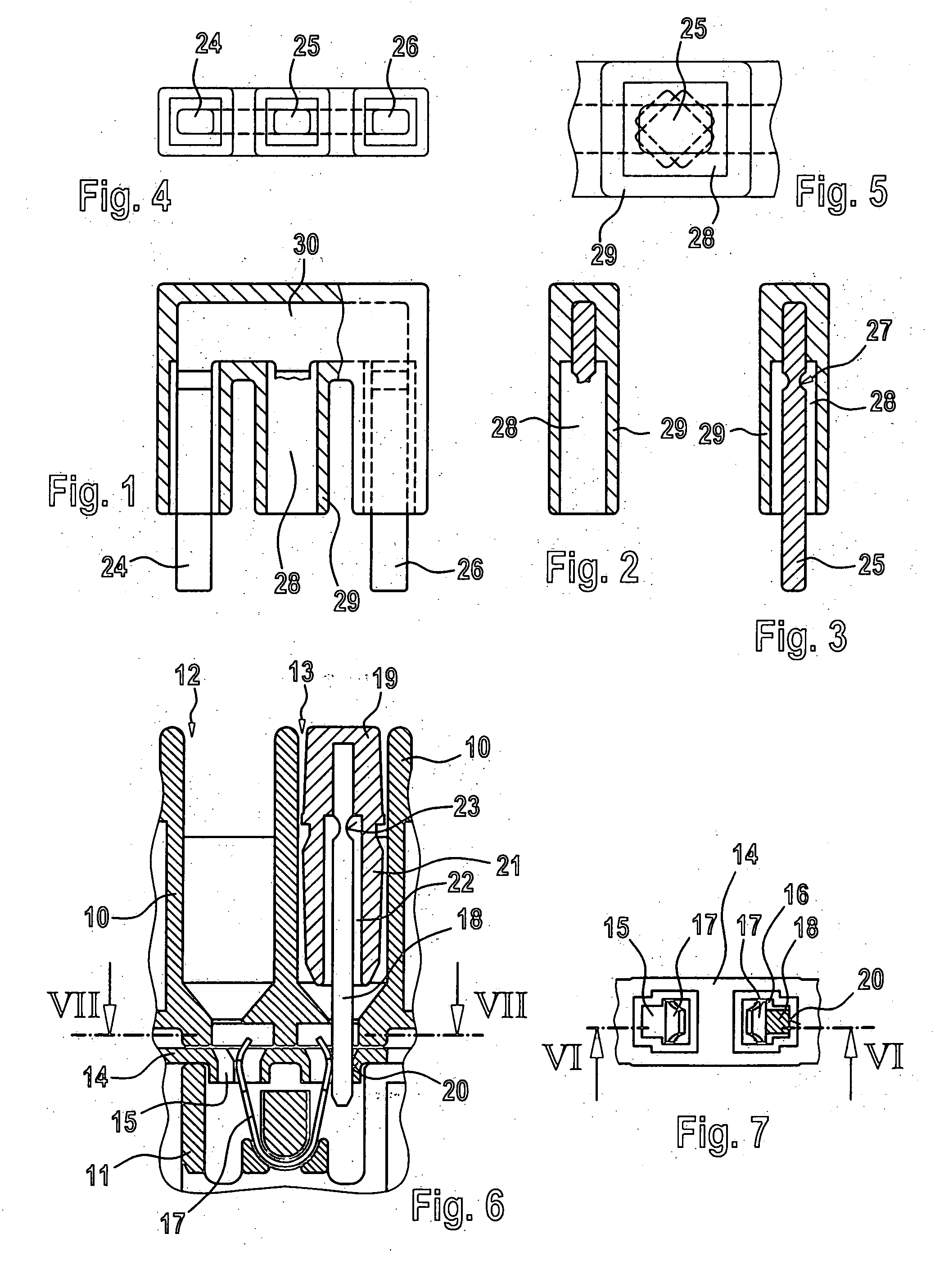
[0020] The excerpt shown in FIG. 6 shows a cross section through the housing of insulation material 10, 11 of a series terminal, which has two bridging recesses of shafts 12 and 13, each of which extends in the direction perpendicular to the plane of the drawing over several series terminals arranged in a row next to each other in a row arrangement of terminals. In FIG. 6, a bridging member 19 occupies only the right bridging shaft 13; the left bridging shaft is empty.

[0021] A current bus 14 is disposed in the housing of insulating material of the series terminals and fixed in position. It possesses two connector receptacles 19 and 16 (see also for this the top view onto the current bus 14 in FIG. 7). The connector receptacles are spring-loaded by means of the spring 17 bent in U-shape. The U-shaped spring 17 is inserted pre-tensed in the connector receptacles and has the task of pressing the connecting pin 18 of the bridging member 19 plugged into the right bridging shaft 13, in a...


PUM


Abstract

A bridging member for electrical terminals provides each of the connecting pins of the bridging member with a sleeve of insulating material, which extends in the axial direction around the connecting pin in such a way that an inner free space is present between the connecting pin and the sleeve of insulating material, whereby the connecting pin possesses a material constriction in the depth of the sleeve of insulating material. The connecting pin can execute equilibrating movements in the free space of the sleeve of insulating material and also can be removed from the sleeve of insulating material by means of a rotational movement.

Description

TECHNICAL FIELD [0001] The invention concerns a crossbridging member for electrical terminals which are disposed adjacent to one another in a row, such as, e.g. series terminals which are arranged in a row one after the other on a mounting bus. BACKGROUND DISCUSSION [0002] It is known to provide the current bus of the terminals with connector receptacles, which are positioned centrally symmetric to a common plane of connector receptacles which extends in the direction of the row of terminals. This connector receptacle plane in the usual case runs in a so-called “bridging shaft”, which is formed constructively in the housings of insulating material for the terminals in the row arrangement. [0003] The bridging members are produced as multiple bridging members, i.e., they possess two or more connecting pins which extend but away from the bridge head of the bridging member like a comb and are centrally symmetric to a common comb extension plane, whereby the comb extension plane is equal...

Claims


Application Information

Patent Timeline
Patent Type & Authority Applications(United States)
IPC IPC(8): H01R31/08H01R9/26H01R12/00H01R13/658H01R43/18
CPCH01R13/6599H01R43/18H01R31/08
Inventor KOLLMANN, HANS-JOSEF
Owner WAGO VERW GMBH
Why Eureka
Try Eureka