Cooling scheme for scramjet variable geometry hardware

a technology of variable geometry and cooling scheme, which is applied in the direction of continuous jet plants, efficient propulsion technologies, machines/engines, etc., can solve the problem that significant heat load can be generated on the exterior surface as well

Inactive Publication Date: 2005-10-27
AEROJET ROCKETDYNE INC
View PDF5 Cites 2 Cited by
  • Summary
  • Abstract
  • Description
  • Claims
  • Application Information

AI Technical Summary

Benefits of technology

[0008] It is a further object of the present invention to provide a cooling system which allows substantially uniform coolant flow distribution and collection through a movable element with substantially no stagnant-or cooling starved areas.
[0009] It is still a further object of the present invention to provide a cooling system which has particular utility in cooling a movable cowl inlet flap used in a scramjet engine.

Problems solved by technology

Since the flight trajectory of a hypersonic vehicle can include a number of different cowl flap positions, a significant heat load can be generated on the exterior surface as well.
Designing a movable cowl flap for a scramjet engine presents many challenges.
Actively cooling the flap structure represents one of these challenges.

Method used


Image

  • Cooling scheme for scramjet variable geometry hardware
  • Cooling scheme for scramjet variable geometry hardware
  • Cooling scheme for scramjet variable geometry hardware

Examples


Embodiment Construction

)

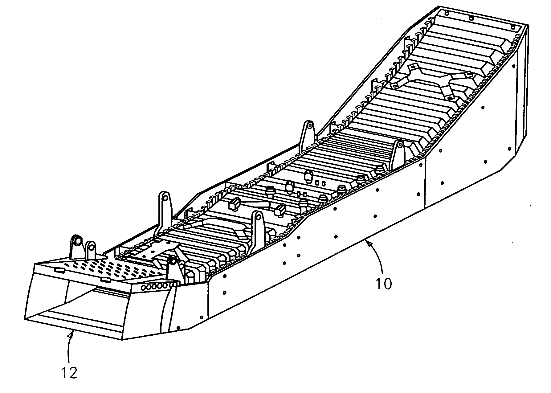
[0027] Referring now to the drawings, FIG. 1 illustrates a scramjet engine 10 having a movable cowl inlet flap 12.

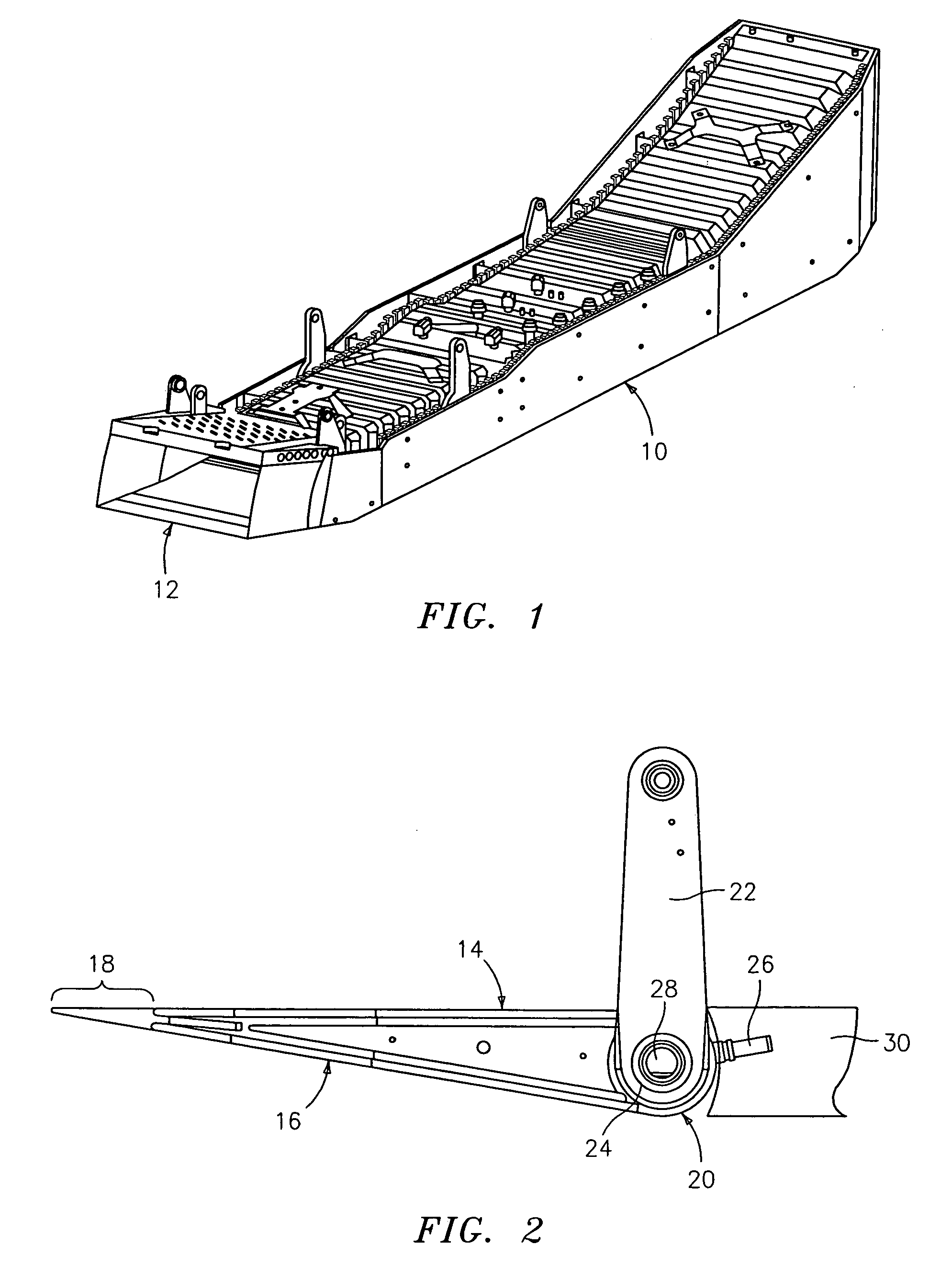
[0028] As can be seen in FIG. 2, the movable cowl inlet flap 12 is a wedge shaped structure having actively cooled internal and external flowpath panels 14 and 16 respectively. A passively cooled composite structure 18 comprises the flap leading edge. Sandwiched between the actively cooled internal and external panels 14 and 16 are laterally and axially directed stringers (not shown). The stringers interface with a torque tube 20 to form the primary structural components of the flap 12.

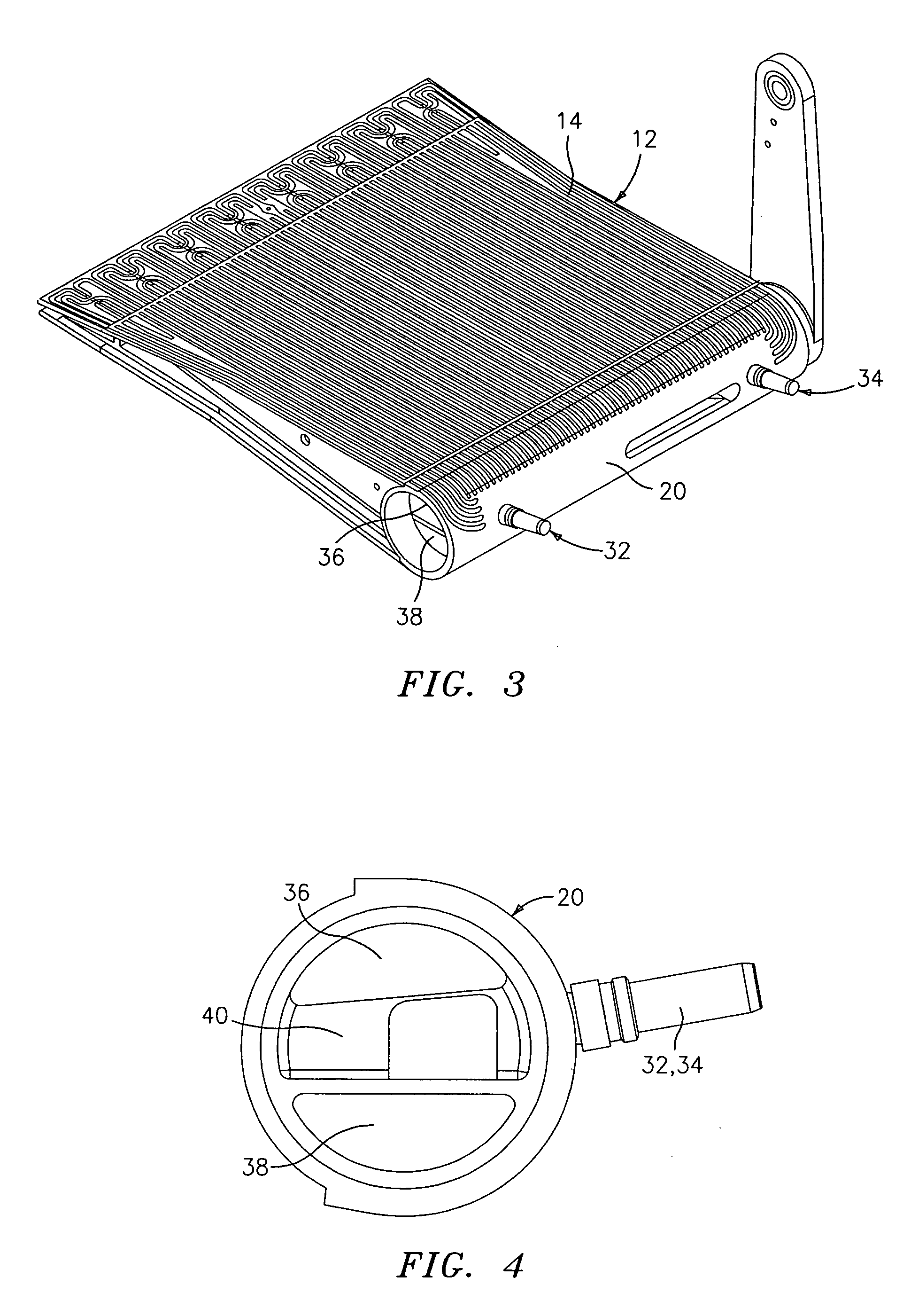
[0029] In addition to being a structural member, the torque tube 20 features a geometry that allows its internal volume to double as both an inlet and exit coolant manifold 36 and 38 respectively (see FIGS. 3 and 4). Torque arms 22, which attach to opposite sides of the torque tube 20, are used to move the movable cowl inlet flap 12 through its intended range of motion. The movable cowl...


PUM


Abstract

A cooling system for use in an engine having an element to be cooled includes at least one cooling channel on a first side of the element, at least one cooling channel on a second side of the element, and the at least one cooling channel on the first side communicating with the at least one channel on the second side in a nose region of the element so as to form a cooling circuit. The cooling system has particular utility in cooling interior and exterior surfaces of a movable cowl inlet flap used in a scramjet engine.

Description

BACKGROUND OF THE INVENTION [0001] (1) Field of the Invention [0002] The present invention relates to a cooling system for use in an engine having a movable element which requires cooling. The cooling system of the present invention has particular utility in scramjet engines where a movable cowl inlet flap requires cooling. [0003] (2) Prior Art [0004] As supersonic combustion ram jet (scramjet) engine technology continues to develop, an important goal will be to improve the propulsion system's operability and performance. One method of achieving this goal is to incorporate variable geometry into the engine flowpath design. Variable geometry allows for real time optimization of the engine flowpath lines for varying flight conditions. Incorporating a movable cowl inlet flap is one method of achieving variable geometry in a scramjet engine. [0005] The operating environment of the cowl flap requires the metallic flowpath surface of the flap to be actively cooled. Since the flight trajec...

Claims


Application Information

Patent Timeline
Patent Type & Authority Applications(United States)
IPC IPC(8): F02K1/00F02K7/10F02K7/14
CPCF02C7/042F02K1/822F05D2220/10Y02T50/672Y02T50/675F02K7/10Y02T50/60
Inventor CUVA, WILLIAM J.PAULUS, DONALD E.
Owner AEROJET ROCKETDYNE INC
Why Eureka
Try Eureka