
Nail magazine structure of a power nailer

Inactive Publication Date: 2005-10-27
HONG WEN QING
View PDF5 Cites 4 Cited by
  • Summary
  • Abstract
  • Description
  • Claims
  • Application Information

AI Technical Summary

Benefits of technology

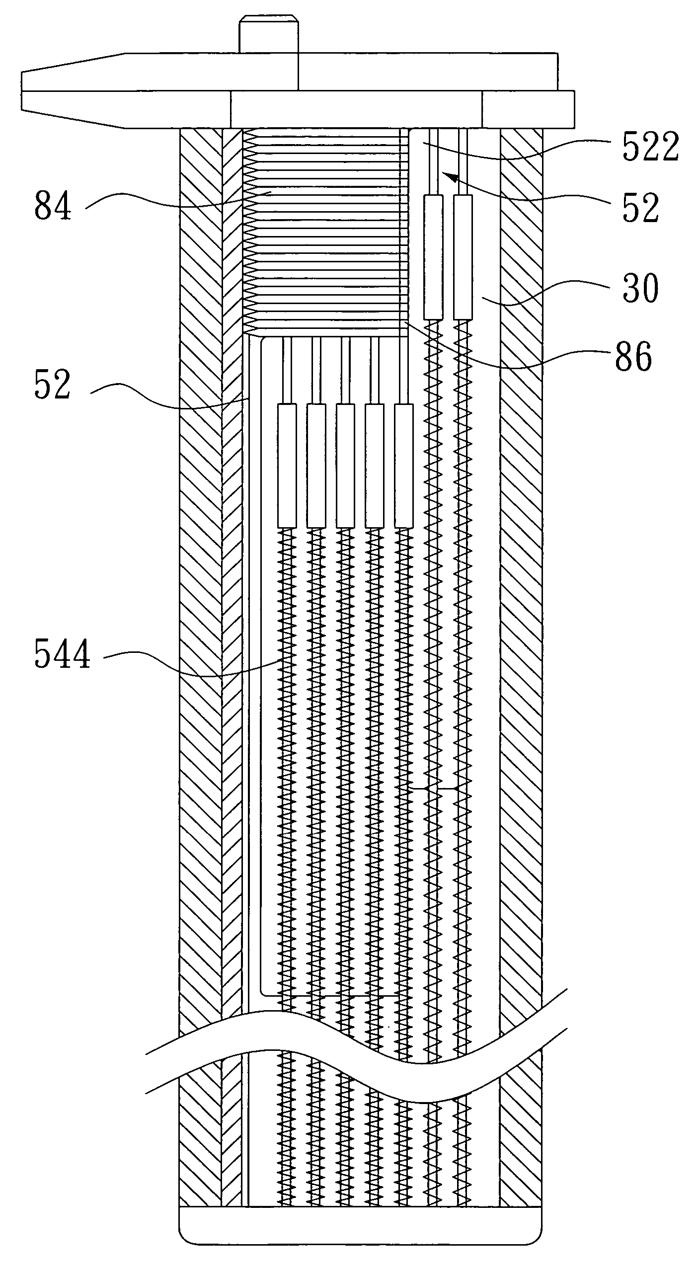
[0007] It is an object of the present invention to provide a nail magazine structure of a power nailer having the following advantages: a row of nails which can be stably disposed and removed, and the cost of manufacture and the volume of the whole power nailer that don't be increased.

Problems solved by technology

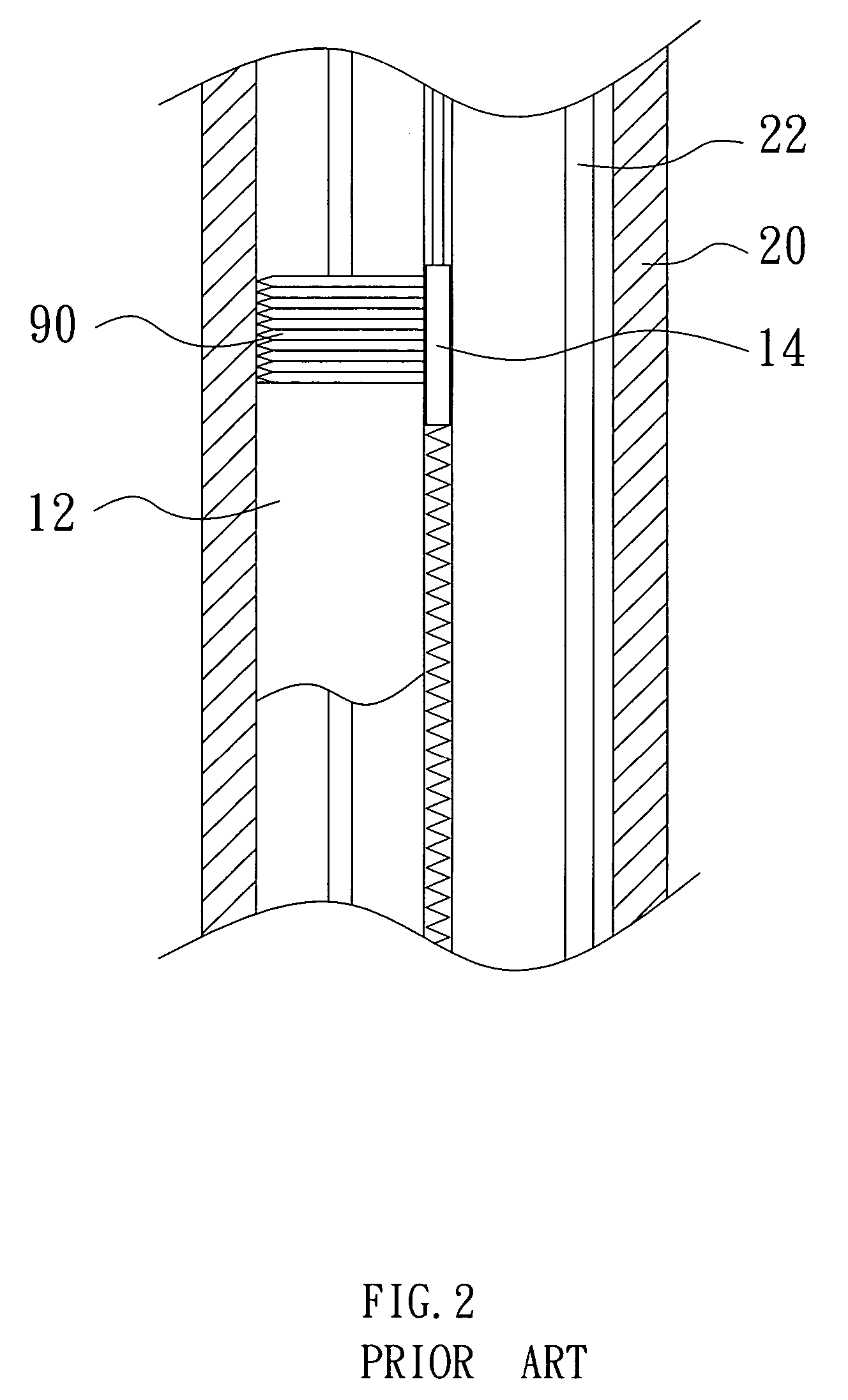
If the length of the constraining portion 14 is increased, the length of the sliding groove 22 must be simultaneously increased, such that the volume of the whole power nailer can be much increased and the cost of manufacture is also increased.

Method used


Image

  • Nail magazine structure of a power nailer
  • Nail magazine structure of a power nailer
  • Nail magazine structure of a power nailer

Examples


Embodiment Construction

[0015] Referring to FIG. 3, it depicts a nail magazine including a first magazine sheet 30, a second magazine sheet 40, a plurality of nail pushing units 50 and a nailer nozzle 60. An end of the first magazine sheet 30 is joined with the nailer nozzle 60, and the second magazine sheet 40 is disposed on the first magazine sheet 30 and relative to the first magazine sheet 30 to move. It is noted that a surface of the first magazine sheet 30 is flat, but the second magazine sheet 40 provided with a plurality of grooves 42 disposed in a surface thereof.

[0016] The nail pushing unit 50 includes a pushing sheet 52 and a flexible element 54. The flexible element 54 is disposed in the grooves 42 of the second magazine sheet 40. The combination of the pushing sheet 52 and the flexible element 54 is disposed between the first magazine sheet 30 and the second magazine sheet 40, and the plurality of nail pushing units 50 are parallel to one another and are disposed between the first magazine sh...


PUM


Abstract

A nail magazine structure of a power nailer includes a first magazine sheet, a second magazine sheet disposed on the first magazine sheet, and a plurality of nail pushing units parallel to one another and disposed between the first magazine sheet and the second magazine sheet for pushing a row of nails disposed in the nail magazine. The nail pushing unit includes a pushing sheet, a flexible element, and a supporting portion disposed at a side of the pushing sheet for near supporting an end of the row of nails, such that the row of nails can be stably disposed in the nail magazine and be stably removed.

Description

FIELD OF THE INVENTION [0001] The present invention relates to a nail magazine structure, and more particularly to a nail magazine structure of a power nailer having an interior for deposing a row of nails and including a plurality of pushing sheets for pushing the row of nails into a nailer nozzle. BACKGROUND OF THE INVENTION [0002] A power nailer is the tool which shoots a nail to a work piece to be nailed by utilizing high pressure air to driving a piston and a firing pin. The power nailer mainly includes a main body, a nailer nozzle and a nail magazine. The main body is provides with the piston and the firing pin which are disposed in the main body. An end of the nailer nozzle is joined with the main body, and a side of the nailer nozzle is joined with the nail magazine. A plurality of nails are disposed in the nail magazine, and a plurality of nail pushing unit are disposed in the nail magazine for being corresponding to the nails with different length and pushing the nails int...

Claims


Application Information

Patent Timeline
IPC IPC(8): B25C5/02B25C5/16
CPCB25C5/1617
Inventor HONG, WEN-QING
Owner HONG WEN QING
Learn More