Transmission mechanism for a dynamic ornament

Inactive Publication Date: 2005-10-27
HSU LIEH LIANG
View PDF6 Cites 4 Cited by
  • Summary
  • Abstract
  • Description
  • Claims
  • Application Information

AI Technical Summary

Benefits of technology

[0006] Accordingly, an object of the present invention is to provide a transmission mechanism for a dynami

Problems solved by technology

However, a conventional transmission mechanism for a dynamic ornament cannot ensure smooth and stable operation, which adversely affects the

Method used


Image

  • Transmission mechanism for a dynamic ornament
  • Transmission mechanism for a dynamic ornament
  • Transmission mechanism for a dynamic ornament

Examples


Example

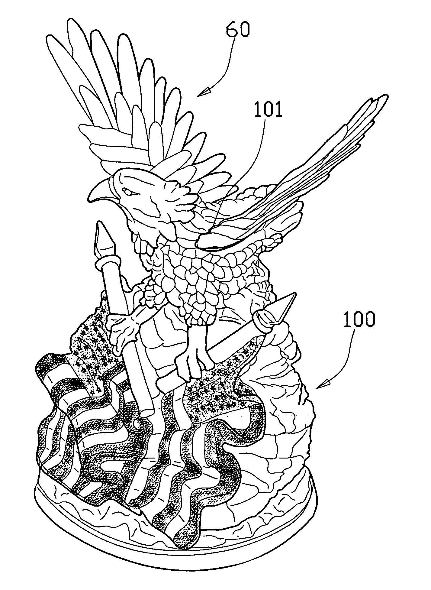
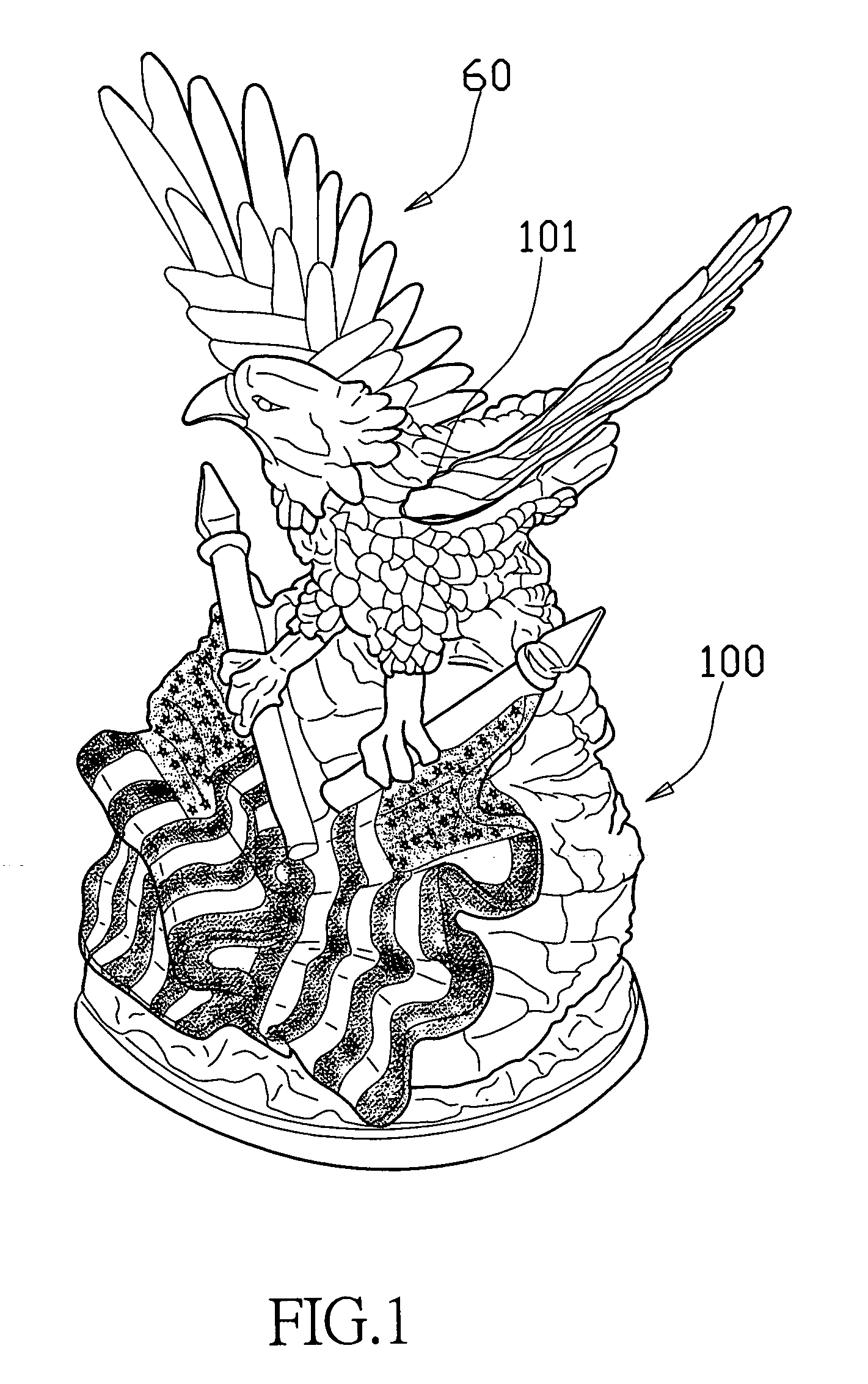
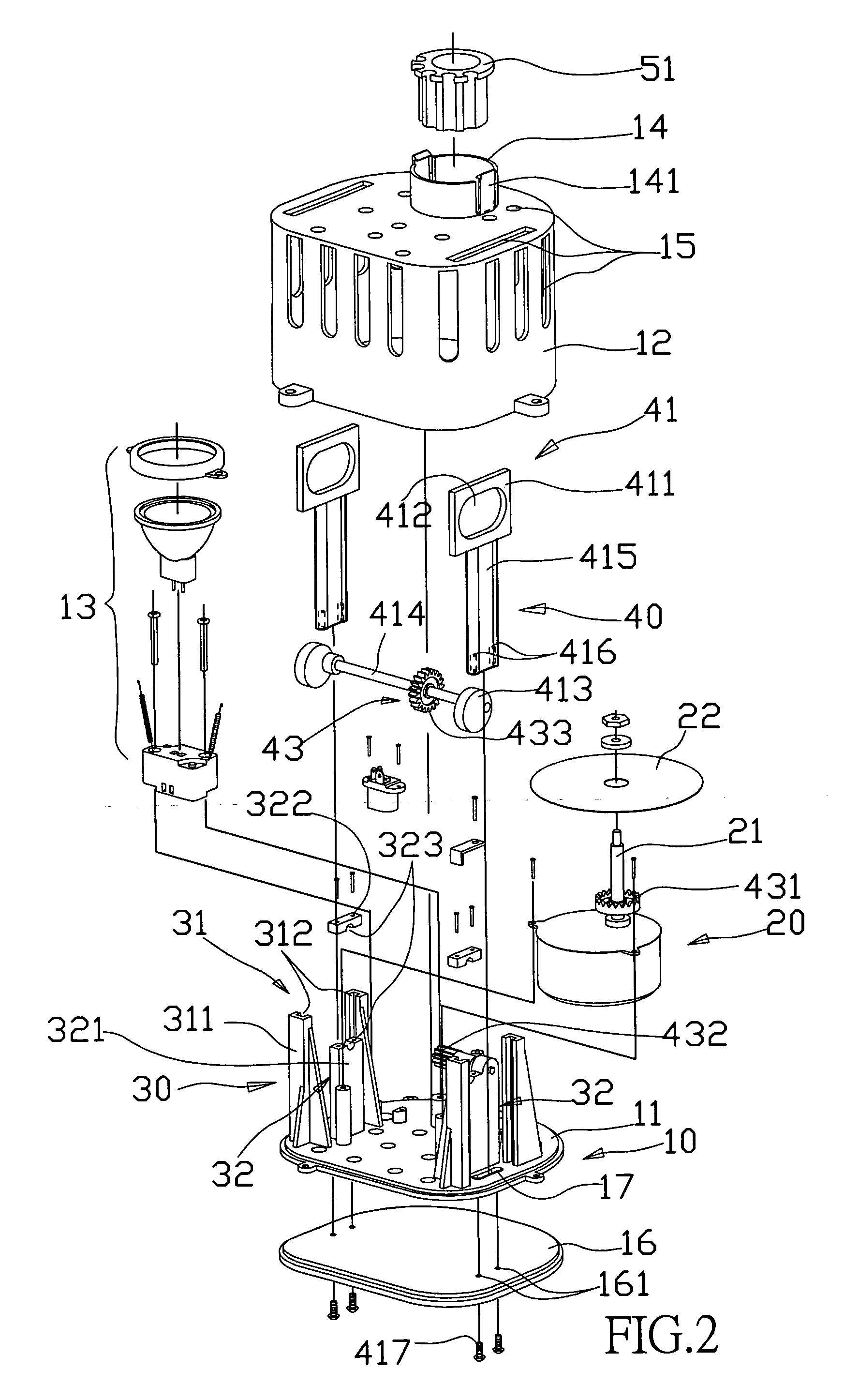
[0027] Referring to FIGS. 1-3, a transmission mechanism for a dynamic ornament of the present invention includes a housing 10, a motor 20, a transmission seat assembly 30 and a transmission device 40. The housing 10 includes a base 11, a top cover 12 and a bottom cover 16. A lamp 13 is fixed to the base 11. A pair of slots 17 is defined in opposite sides of the base 11. The top cover 12 and the base 11 are threadedly fixed together and cooperatively define a receiving space for receiving the motor 20, the transmission seat assembly 30 and the transmission device 40. A receiving post 14 extends from the top cover 12 for receiving an ornament sleeve 51 which is used to connect with movable parts of the dynamic ornament. A pair of latches 141 is formed oppositely at the receiving post 14 for fixing the ornament sleeve 51 to the receiving post 14. A plurality of openings 15 with different sizes is defined in the top cover 12 for allowing light to pass therethrough and saving material. A...


PUM


Abstract

A transmission mechanism for a dynamic ornament includes a housing including a base, a motor fixed to the base with a motor shaft extending therefrom, a transmission seat assembly fixed to the base and including a pair of first seats connected to the base, and a transmission device connected to the transmission seat assembly and including a sliding set and a gear set. The sliding set includes a pair of mating portions slidable along the first seats, a pair of connecting portions connecting with the mating portions, a pair of eccentrics and a transmission shaft connected between the eccentrics and rotatably connected to the transmission seat assembly. A mating hole is defined in each of the mating portions for rotatably receiving the eccentric therein. The gear set connects between the motor and the transmission shaft of the sliding set thereby driving the transmission shaft to rotate.

Description

BACKGROUND OF THE INVENTION [0001] 1. Field of the Invention [0002] The present invention relates to a transmission mechanism, and particularly to a transmission mechanism for a dynamic ornament. [0003] 2. PRIOR ART [0004] There are many kinds of ornaments, most of which are static ornaments. Since a dynamic ornament can change the tedious nature of a static environment and have a visually pleasing effect, the dynamic ornament is obviously more attractive. In general, the dynamic ornament has a transmission mechanism therein to drive movable parts thereof to perform a predetermined cyclical motion. [0005] However, a conventional transmission mechanism for a dynamic ornament cannot ensure smooth and stable operation, which adversely affects the dynamic effect of the ornament or even cannot provide the dynamic effect. Furthermore, the conventional transmission mechanism is complicated. SUMMARY OF THE INVENTION [0006] Accordingly, an object of the present invention is to provide a tran...

Claims


Application Information

Patent Timeline
IPC IPC(8): A63H1/00G09F19/02
CPCG09F19/02
Inventor HSU, LIEH-LIANG
Owner HSU LIEH LIANG
Why Eureka
Try Eureka