Form frame for concrete footings

Inactive Publication Date: 2005-11-03
CM&M IND
View PDF21 Cites 7 Cited by
  • Summary
  • Abstract
  • Description
  • Claims
  • Application Information

AI Technical Summary

Benefits of technology

[0004] The present invention overcomes the drawbacks of these prior attempts to constrain the forms to the desired width. The present invention provides a steel frame of high strength that extends between the inner and outer form walls and prevents the form walls from bowing inwardly and narrowing the footing, and prevents the forms from blowing out. The steel frame is adjustable to accommodate form widths from 16 inches or less to 24 inches or more. The steel frame is

Problems solved by technology

Problems occur when the concrete confined between the inner and outer walls exerts a force on the forms pushing them apart until they collapse under the force resulting in what's known as a blowout.
Blowouts not only cause loss of money to the contractor due to the loss of the concrete that escapes the forms, but much labor is needed to clean up the blowout and to reset the forms.
Another problem that is encountered when pouring the footings is that the top edges of the forms sometimes tend to curve inward toward each other due to the forces pushing outwardly at the bottom edges of the forms.
This can res

Method used


Image

  • Form frame for concrete footings
  • Form frame for concrete footings
  • Form frame for concrete footings

Examples


Embodiment Construction

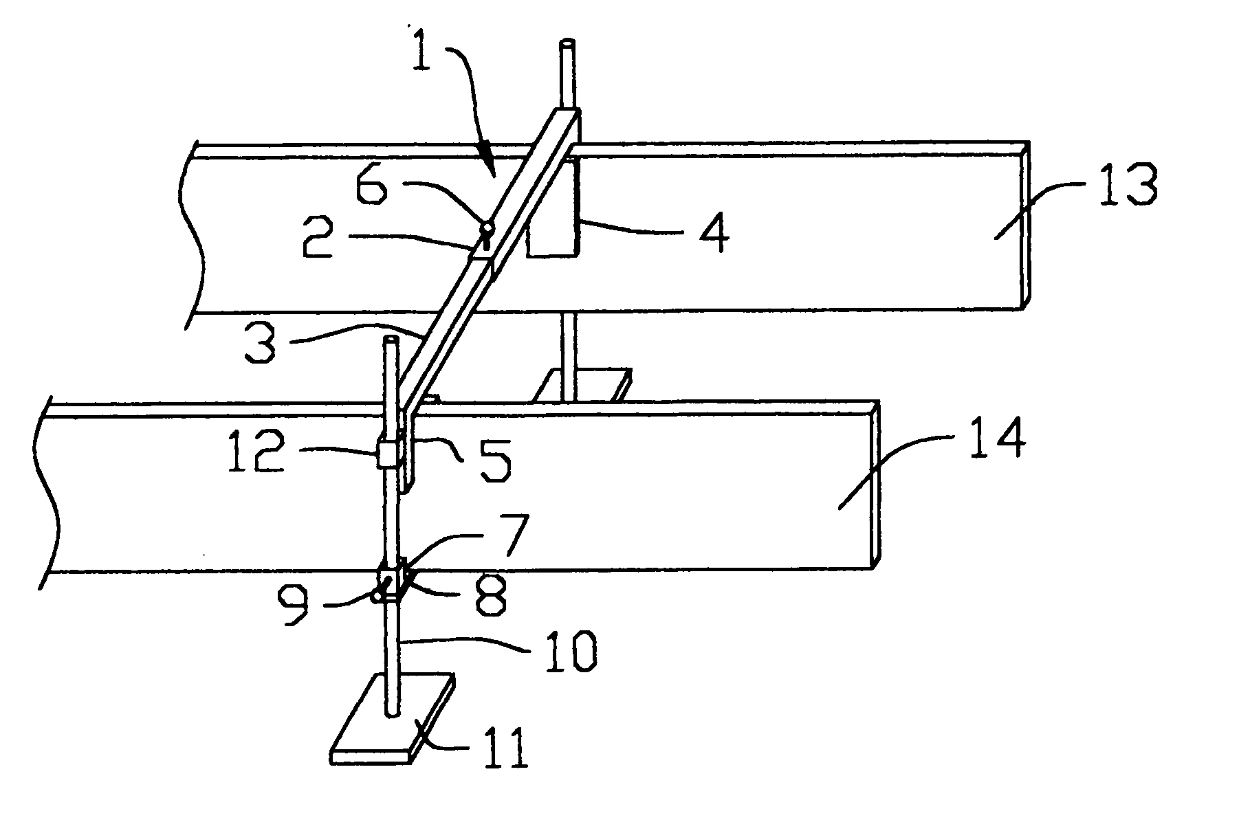
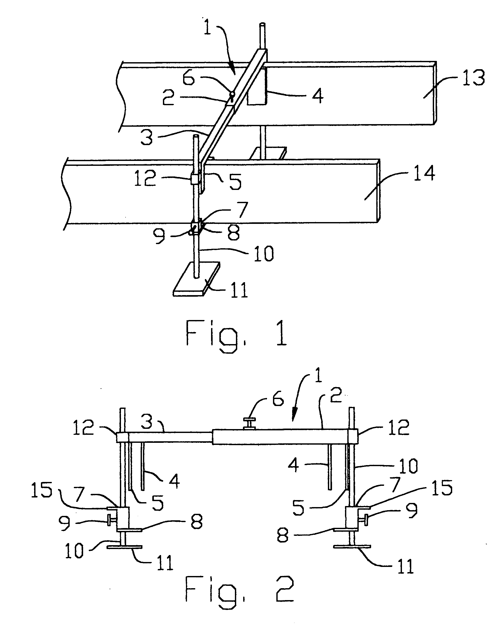
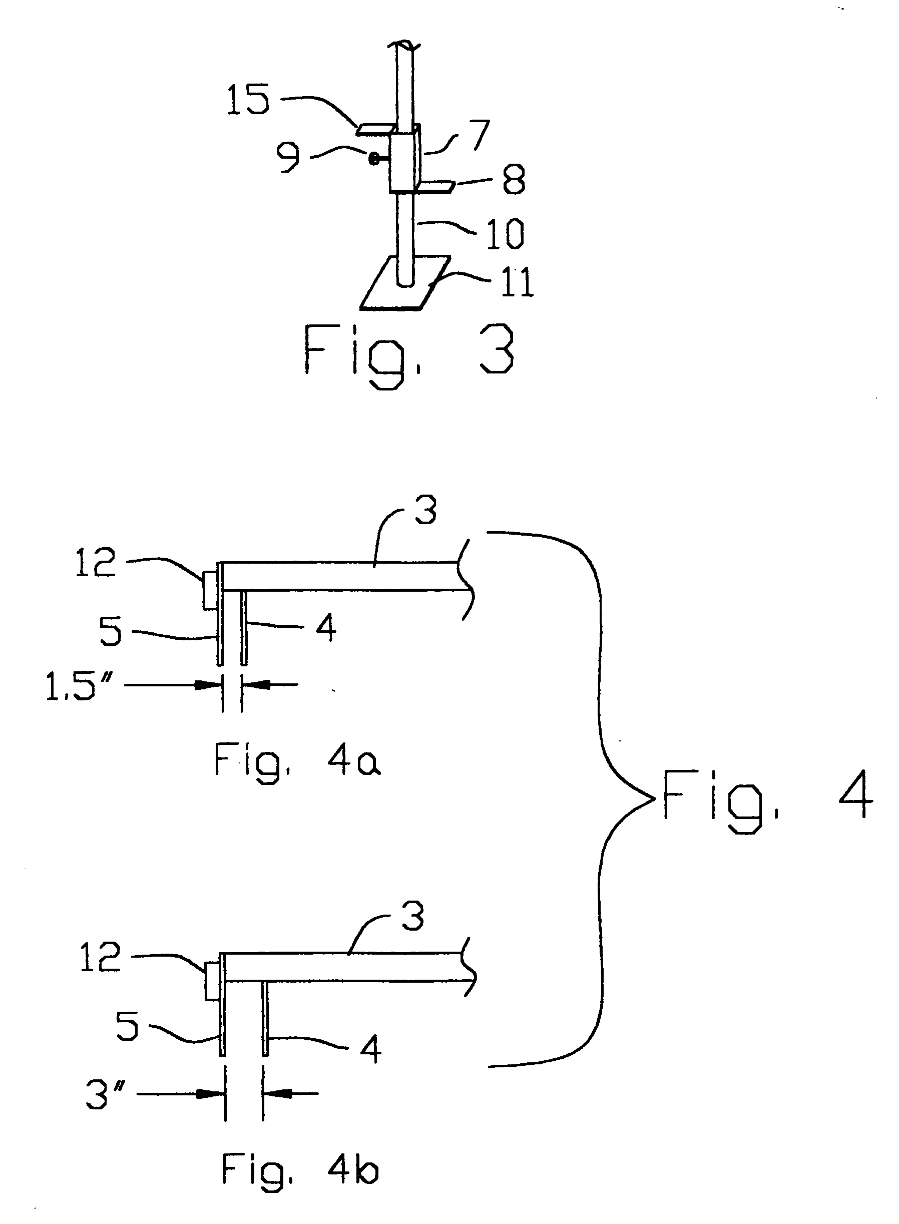
[0011] Referring to FIG. 1, frame 1 is shown in use on concrete footing forms 13 and 14. Forms 13 and 14 are typically made of dimensional lumber, but may be made of heavy weight plywood or even of lightweight metal such as aluminum. Form 14 determines the inner wall of the concrete footing while form 13 determines the outer wall of the concrete footing. Frame 1 consists of square tubular steel member 3 which telescopically slides within square tubular steel member 2, allowing for adjustment of the frame 1 to accommodate any width of form setup. Once adjusted to the desired width, locking screw 6 is tightened through member 2 and against member 3 to lock member 3 in fixed position relative to member 2. Tubular steel member 3 could also have holes or indents at fixed positions along its length to allow for specific adjustments, such as widths of 16 inches, 18 inches, 24 inches, etc. Tubular steel members 2 and 3 each have at their outer ends bracket members 4 and 5. FIG. 2 shows deta...


PUM


Abstract

A square tubular steel frame extends between inner and outer concrete footing form walls and prevents the inner and outer form walls from bowing inwardly and causing an undesirable narrow footing width, or bowing outwardly and causing a form blowout. The steel frame is adjustable in width to accommodate the narrowest to the widest footings. A lower bracket supports the bottom of the form, and is adjustable in height. Each end of the frame is replaceable to accommodate a single form thickness, or to accommodate overlapping forms. The frame is reusable, easy to set up, and simple to take down and move to the next job, and is safe to use.

Description

BACKGROUND OF THE INVENTION [0001] The present invention relates to the masonry field, especially to the art of laying up forms in which concrete footings are poured. Forms for concrete footings are set up with an inner and outer wall and are usually made of dimensional lumber or heavy plywood panels, or may even be manufactured aluminum panels. The inner and outer walls confine the liquid concrete and give it its final shape and dimension. Depending on the type of structure being set on these footings, the inner and outer walls may be spaced apart 12 inches, 16 inches, 24 inches or wider. Problems occur when the concrete confined between the inner and outer walls exerts a force on the forms pushing them apart until they collapse under the force resulting in what's known as a blowout. Blowouts not only cause loss of money to the contractor due to the loss of the concrete that escapes the forms, but much labor is needed to clean up the blowout and to reset the forms. [0002] Another p...

Claims


Application Information

Patent Timeline
IPC IPC(8): E04B2/00E04G13/00E04G17/12
CPCE04G17/12E04G13/00
Inventor ALBANO, ROCCHINO
Owner CM&M IND
Why Eureka
Try Eureka