Chua's circuit and it's use in a hyperchaotic circuit

a hyperchaotic circuit and circuit technology, applied in the field of chuas circuits, can solve the problems of system trajectory sensitiveness, inefficient power consumption of final circuit, and bulky final circui

Active Publication Date: 2005-11-03
STMICROELECTRONICS PVT LTD
View PDF0 Cites 12 Cited by
  • Summary
  • Abstract
  • Description
  • Claims
  • Application Information

AI Technical Summary

Benefits of technology

[0027] To achieve the above objectives, the present invention provides an improved Chua's circuit providing current mode operation, access to all state variables, minimum use of grounded passive elements, and freedom from passive component matching. The Chua's circuit comprises a multiple output current conveyer based inductor having one grounded terminal, a capacitor connected across the second terminal of the inductor, and a resistor having one terminal connected to the second terminal of the inductor. The second terminal of the resistor may be connected to one terminal of a second capacitor. The other end of the second capacitor may be grounded. A pair of multiple output current conveyers may be connected together to form a 2-terminal negative resistance having one terminal connected to ground and the second terminal connected to the second terminal of the resistance. The multiple output current conveyers may be the multiple output (second generation) current conveyers (MO-CCII).
[0030] An improved Chua's circuit may provide current mode operation, access to all state variables, minimum use of grounded passive elements, and freedom from passive component matching. The Chua's circuit comprises a dual output current conveyer based inductor having one grounded terminal, a capacitor connected across the second terminal of the inductor, and a resistor having one terminal connected to the second terminal of the inductor. The second terminal of the resistor may be connected to one terminal of a second capacitor, the other end of which is grounded. A pair of dual output current conveyers may be connected together to form a 2-terminal negative resistance having one terminal connected to ground, and the second terminal connected to the second terminal of the resistance. The dual output current conveyer may be a dual output (second generation) current conveyer.
[0034] A method for improving a Chua's circuit to provide a current mode operation, access to all state variables, minimum use of grounded passive elements, and freedom from passive component matching is provided. The method may comprise the steps of simulating a grounded inductor using a multiple output current conveyer, connecting a capacitor connected across the second terminal of the inductor, and connecting one terminal of a resistor to the second terminal of the inductor. The second terminal of the resistor is connected to one terminal of a second capacitor, the other end of which is grounded. The method further includes providing a 2-terminal negative resistance device using a pair of multiple output current conveyers.

Problems solved by technology

However, to an observer it looks mainly like noise.
Also, such a system's trajectory is sensitive to initial conditions.
All the above architectures individually provide advantages of a Chua's circuit, but so far, there is no circuit that simultaneously provides: current mode operation; use of minimum grounded passive elements; availability of all the state variables; availability of two state variables in the form of current which can be used to further generate other complex chaotic circuits; a circuit free from passive component matching; use of lesser active components as compared to that represented by FIG. 2; and generation of a reduced hardware higher order chaotic circuit (also called a hyper-chaotic circuit) using one of the available currents mentioned above.
However, the use of any of these circuits will not only add to the disadvantage of those proposed Chua's circuits, but also one voltage buffer and one floating resistor per coupling is required, which in turn, makes the final circuit bulky and inefficient in terms of power consumption.

Method used


Image

  • Chua's circuit and it's use in a hyperchaotic circuit
  • Chua's circuit and it's use in a hyperchaotic circuit
  • Chua's circuit and it's use in a hyperchaotic circuit

Examples


Embodiment Construction

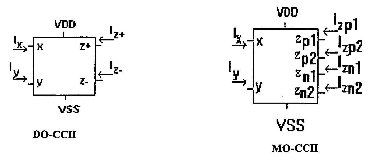
[0053] The invention provides a Chua's circuit using a Dual Output (second-generation) Current Conveyer (DO-CCII) as one embodiment. The invention also provides implementation of a Chua's circuit using a Multiple Output Current Conveyor (MO-CCII), and provides a hyper-chaotic circuit using the Multiple Output Current Conveyor.

[0054]FIG. 3 shows the coupling of n Chua's circuits to achieve synchronization. The system thus formed is used to solve the following set of equations: C1⁢ⅆvC1(1)ⅆt=G⁡(vC2(1)-vC1(1))-f⁡(vC1(1))C2⁢ⅆvC2(1)ⅆt=G⁡(vC1(1)-vC2(1))+iL(1)+f⁡(vC1(1))+1RK⁢(vC2(2)-vC2(1))L⁢ⅆvL(1)ⅆt=-vC2(1)C1⁢ⅆvC1(2)ⅆt=G⁡(vC2(2)-vC1(2))-f⁡(vC1(2))C2⁢ⅆvC2(2)ⅆt=G⁡(vC1(2)-vC2(2))+iL(2)+f⁡(vC1(2))+1RK⁢(vC2(3)-vC2(2))L⁢ⅆvL(2)ⅆt=-vC2(2)⋮C1⁢ⅆvC1(n)ⅆt=G⁡(vC2(n)-vC1(n))-f⁡(vC1(n))C2⁢ⅆvC2(n)ⅆt=G⁡(vC1(n)-vC2(n))+iL(n)+f⁡(vC1(n))+1RK⁢(vC2(n+1)-vC2(n))L⁢ⅆvL(n)ⅆt=-vC2(n)

[0055] The dynamics of the system is dependent on the controlling resistor RK. This aspect has been discussed in the prior art.

[0056...


PUM


Abstract

The present invention provides an improved Chua's circuit providing current mode operation, access to all state variables, minimum use of grounded passive elements, and freedom from passive component matching comprising a dual output current conveyer based inductor having one grounded terminal, a capacitor connected across the second terminal of said inductor, a resistor having one terminal connected to the second terminal of said inductor, the second terminal of said resistor connected to one terminal of a second capacitor the other end of which is grounded, and a pair of dual output current conveyers connected together to form a 2-terminal negative resistance having one terminal connected to ground and the second terminal connected to the second terminal of said resistance.

Description

RELATED APPLICATION [0001] This application is a continuation of Ser. No. 10 / 985,327 filed Nov. 10, 2004, the entire disclosure of which is incorporated by reference herein.FIELD OF THE INVENTION [0002] The invention relates to Chua's circuits, and more particularly, to a Chua's circuit using a Dual Output Current Conveyer (DO-CCII), and to a Chua's circuit using a Multiple Output Current Conveyor (MO-CCII) for generating a hyper-chaotic circuit. BACKGROUND OF THE INVENTION [0003]FIG. 1 shows a generalized Chua's circuit that has a parallel combination of a capacitor C2, a Chua's diode NR1 connected to an L-C tank circuit that includes a second capacitor C1 connected in parallel with a serially connected inductor L1. In addition, a first voltage V1 is defined across capacitor C1 and a second voltage V2 is defined across capacitor C2 with the positive orientation of voltages V1 and V2 both being at the positive end of the corresponding capacitor. Finally, there is a linear resistor R...

Claims


Application Information

Patent Timeline
Patent Type & Authority Applications(United States)
IPC IPC(8): H03F1/34H03H11/00H03H11/52
CPCH03F1/34
Inventor GANDHI, GAURAV
Owner STMICROELECTRONICS PVT LTD
Why Eureka
Try Eureka