Clipped contact whip and flex antenna assembly for a device

a technology of contact whip and antenna assembly, which is applied in the direction of resonant antennas, elongated active element feeds, radiating element structural forms, etc., can solve the problems of difficult mechanical integration of multiple antennas into a device, difficult to provide steady, reliable electrical contact between different antennas and the circuitry of a particular device,

Inactive Publication Date: 2005-11-03
AMPHENOL T & M ANTENNAS
View PDF5 Cites 7 Cited by
  • Summary
  • Abstract
  • Description
  • Claims
  • Application Information

AI Technical Summary

Problems solved by technology

However, it may be difficult to provide steady, reliable electrical contact between different antennas and the circuitry of a particular device.
Further, it may be difficult to mechanically integrate multiple antennas into a device.
Additionally, it may be a challenge to provide such integration while adhering to sometimes rigid volume and area considerations for an antenna assembly, as may be required by certain consumer or manufacturing demands, for example.

Method used


Image

  • Clipped contact whip and flex antenna assembly for a device
  • Clipped contact whip and flex antenna assembly for a device
  • Clipped contact whip and flex antenna assembly for a device

Examples


Embodiment Construction

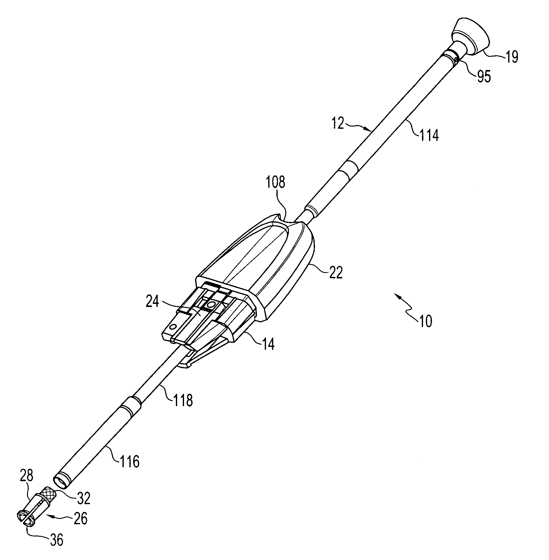
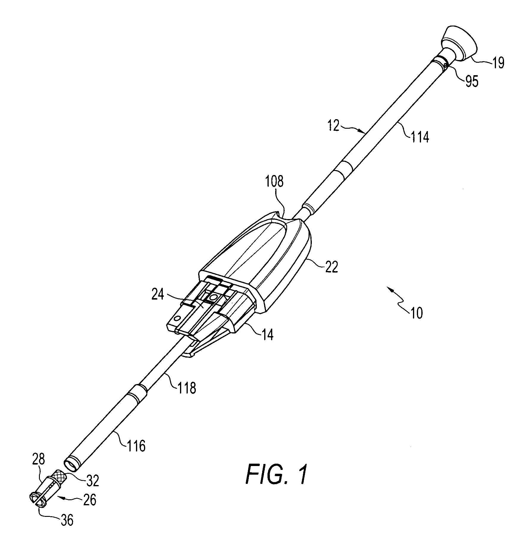
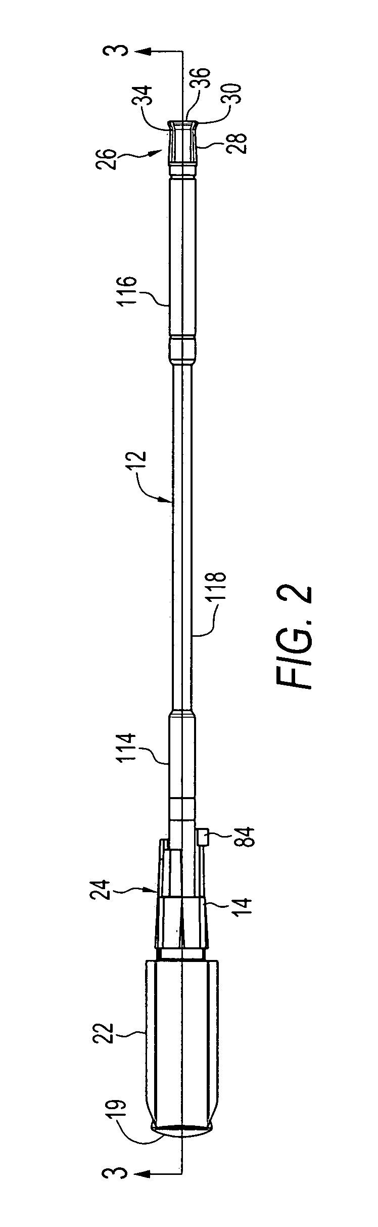
[0030] To improve radio-frequency (RF) reception in a device by, for example, providing multiple antennas to receive signals at various frequencies, it is contemplated to provide an antenna assembly including both an elongated antenna, such as a whip antenna, and a flex antenna. However, it may be difficult to provide an antenna assembly that maintains secure electrical contact between the flex antenna and / or the elongated antenna and the circuitry of the device. Furthermore, it is advantageous to provide an antenna assembly and assembly method that allows repeatable or large-scale production at a reasonable cost.

[0031] A preferred embodiment of the present invention provides, among other things, an antenna assembly for a portable device which includes an elongated antenna such as a whip antenna, a flex antenna, and a conductive mechanism for coupling the whip antenna and the flex antenna to circuitry of the device. Preferably, the flex antenna is wrapped around a base, and include...


PUM


Abstract

Antenna assembly for a portable device. The antenna assembly includes a nonconductive base, a conductive bushing held within a lower end of the base, and a flex antenna wrapped around the base. The flex antenna includes a trace having substantially all of its length disposed around an upper end of the base axially away from the conductive bushing and terminating in a flexible end contact that extends over the bushing. A conductive mechanism engages the conductive bushing and presses the flexible end contact against the bushing. The conductive mechanism includes an exposed elongated contact. A whip antenna extends through the nonconductive base, and includes a nonconductive extension extending from a top end thereof and a lower contact for electrically contacting the bushing when the whip antenna is extended relative to the base.

Description

PRIORITY CLAIM [0001] The present application claims the benefit of U.S. Provisional Application No. 60 / 566,861, filed Apr. 30, 2004, under 35 U.S.C. § 119.FIELD OF THE INVENTION [0002] The present invention relates generally to the field of wireless communication for portable devices. The present invention relates more particularly to the field of antennas. BACKGROUND OF THE INVENTION [0003] It is desirable to enable reception of various radio-frequency bands in a single portable device such as, but not limited to, a wireless communication device or a portable computing device. One potential method of doing so is by using different antennas, each connected to circuitry of the device, respectively receiving one or more different frequency bands. For example, a flex antenna (that is, conductive traces in or on a flexible substrate) and elongated (e.g., whip) antenna may separately be integrated into a single device to allow reception of different frequencies. [0004] However, it may b...

Claims


Application Information

Patent Timeline
Patent Type & Authority Applications(United States)
IPC IPC(8): H01Q1/12H01Q1/24H01Q1/38H01Q9/14H01Q9/30H01Q21/30
CPCH01Q1/1207H01Q1/244H01Q21/30H01Q9/145H01Q9/30H01Q1/38H01Q1/24
Inventor KFOURY, TONYMATHEWS, JIM
Owner AMPHENOL T & M ANTENNAS
Why Eureka
Try Eureka