Broadcasting receiving antenna system mounted in a wireless terminal

a receiving antenna and wireless terminal technology, applied in the direction of resonant antennas, flexible aerials, collapsible antennas, etc., can solve the problems of difficult to raise the output of channel b>8, inconvenient use of a longer antenna, and it is widely believed to be almost impossible to produce terrestrial dmb antennas below 15 cm in length. , to achieve the effect of shortening the antenna length

Active Publication Date: 2007-11-29
SAMSUNG ELECTRONICS CO LTD +1
View PDF3 Cites 7 Cited by
  • Summary
  • Abstract
  • Description
  • Claims
  • Application Information

AI Technical Summary

Benefits of technology

[0015]An aspect of the present invention provides a broadcast receiving antenna system which is mounted in a wireless terminal, to shorten the length of the antenna by making the length of the antenna adjustable.

Problems solved by technology

Since channel 8, which is between channel 7 and channel 9, causes radio interference to affect neighboring channels when its output is increased, it is hard to raise the output of channel 8.
However, since such an antenna is mounted in a wireless terminal which features portability and mobility, it is inconvenient to use a longer antenna.
Up until now it has been widely believed to be almost impossible to produce terrestrial DMB antenna below 15 cm in length.
As the DVB-H utilizes a relatively low frequency band, it generally suffers the same problems as the terrestrial DMB antenna.

Method used


Image

  • Broadcasting receiving antenna system mounted in a wireless terminal
  • Broadcasting receiving antenna system mounted in a wireless terminal
  • Broadcasting receiving antenna system mounted in a wireless terminal

Examples


Embodiment Construction

[0040]Certain exemplary embodiments of the present invention will now be described in greater detail with reference to the accompanying drawings.

[0041]In the following description, the same drawing reference numerals are used to refer to the same elements, even in different drawings. The matters defined in the following description, such as detailed construction and element descriptions, are provided as examples to assist in a comprehensive understanding of the invention. Also, well-known functions or constructions are not described in detail, since they would obscure the invention in unnecessary detail.

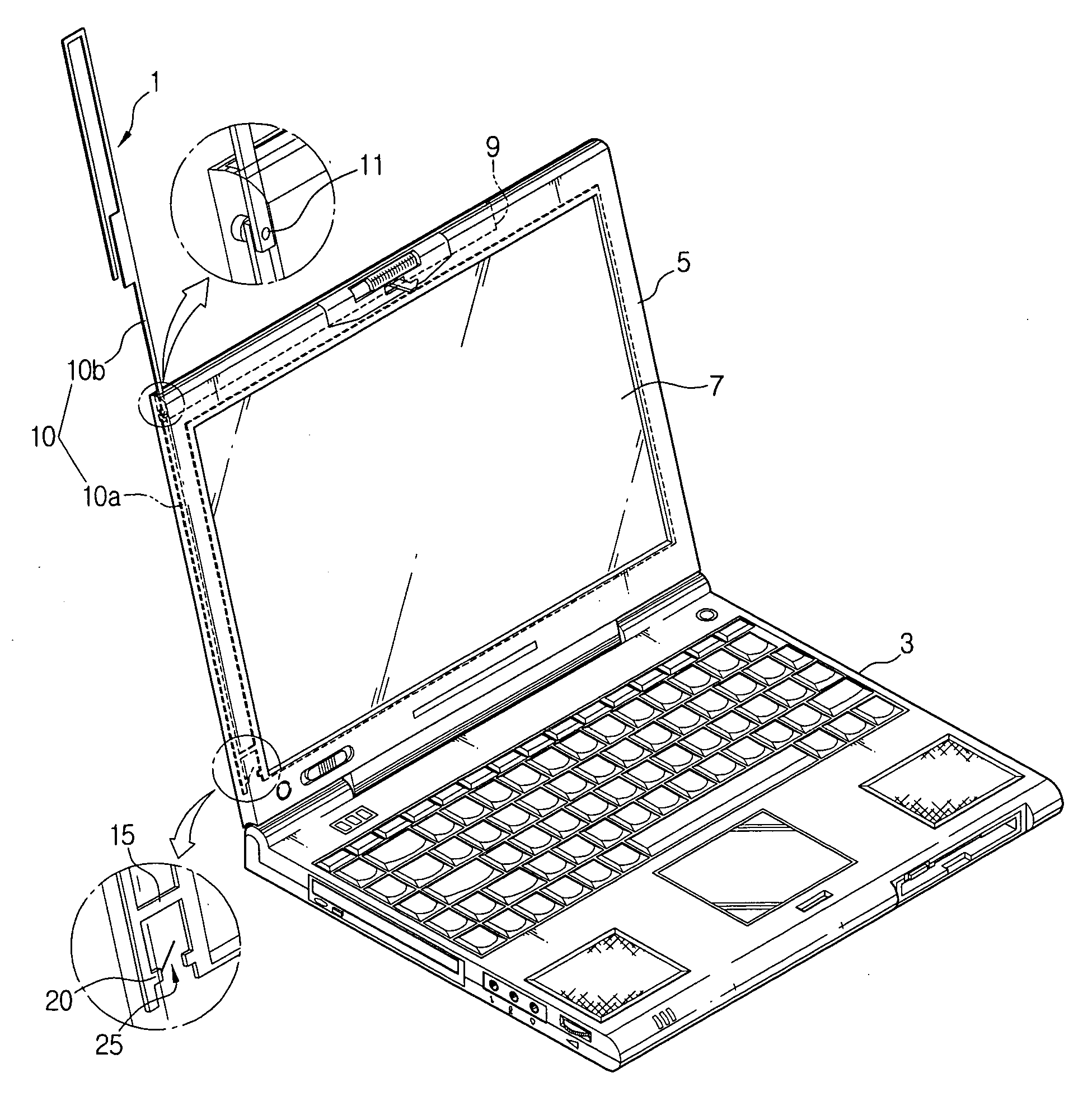
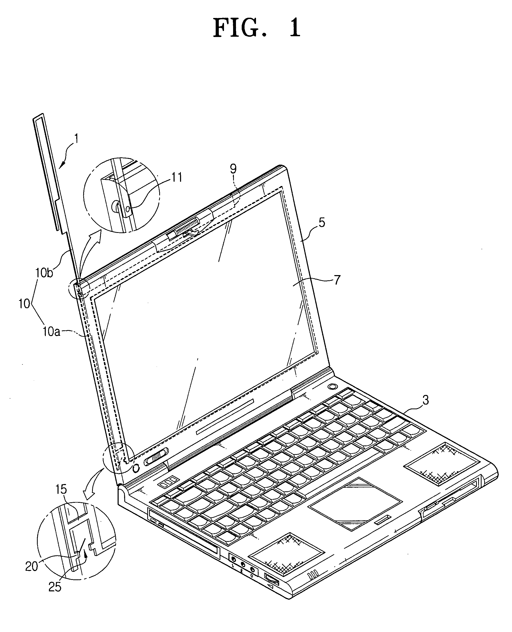
[0042]A broadcast receiving antenna according to an exemplary embodiment of the present invention is mounted in a wireless terminal capable of providing broadcast services such as DMB service or DVB-H service. The broadcast receiving antenna can be embedded in the wireless terminal as an Intenna (Internal antenna), or detachably attached to the exterior of the wireless terminal. It i...


PUM


Abstract

A broadcast receiving antenna system mounted in a wireless terminal. The antenna is bendable, and functions as a PIFA antenna or a monopole whip antenna according to whether it is bent or not. Accordingly, since the length and the type of the antenna are adjustable according to the magnitude of the DMB or DVB-H signal, optimum broadcasting services can be provided and the length of the antenna can be shortened. Ultimately, Intenna-type antenna can be mounted.

Description

CROSS-REFERENCE TO RELATED APPLICATIONS[0001]This application claims priority from Korean Patent Application No. 10-2006-0046365 filed May 24, 2006, in the Korean Intellectual Property Office, the entire disclosure of which is incorporated herein by reference.BACKGROUND OF THE INVENTION[0002]1. Field of the Invention[0003]Systems consistent with the present invention relate to a broadcast receiving antenna system mounted in a wireless terminal. More particularly, the present invention relates to a broadcast receiving antenna system mounted in a wireless terminal, capable of providing optimum services and shortening the antenna length by adjusting the length of the radiating part according to magnitude of electromagnetic waves.[0004]2. Description of the Related Art[0005]With the recent advance of mobile communication technology, mobile terminals are providing various services that have until now been available only in limited places such as the home or office.[0006]Among the various...

Claims


Application Information

Patent Timeline
Patent Type & Authority Applications(United States)
IPC IPC(8): H01Q1/24
CPCH01Q1/08H01Q1/084H01Q9/42H01Q9/0421H01Q9/30H01Q1/22H01Q1/2258H01Q1/2266H01Q1/085H01Q1/2208H01Q1/242H01Q9/40
Inventor KIM, YONG-JINKIM, YOUNG-EILYOON, ICK-JAE
Owner SAMSUNG ELECTRONICS CO LTD
Why Eureka
Try Eureka