
Symmetric, shielded slow wave meander line

a shielded, slow wave technology, applied in the direction of antenna details, antennas, electric long antennas, etc., can solve the problems of more phase shifts per unit length and delay per unit length, and achieve the effects of lowering the resonant frequency of narrow band antennas, lowering the low frequency cutoff limit, and increasing the delay per unit length

Inactive Publication Date: 2005-05-17
R A MILLIER IND INC
View PDF9 Cites 7 Cited by
  • Summary
  • Abstract
  • Description
  • Claims
  • Application Information

AI Technical Summary

Benefits of technology

[0017]In the subject invention, a standard slow wave meander line structure is provided with a top shield. This has a number of important effects. First, the resonant frequency of the device is significantly lowered, which means that its low frequency cutoff is likewise lowered. Secondly, the effective radiation pattern of a meander line loaded antenna has a major horizontal lobe unaffected by ground planes in a wireless device regardless of operating frequency, thus to eliminate down firing. Thirdly, if one wishes to have a frequency switched meander line structure, voltage stress on the switches can be reduced.
[0018]The subject invention is thus a modified a slow wave meander line structure that can be used as a coupling mechanism for 4 MHz transmissions without increasing its size, can be used as a wideband antenna for the 30-88 MHz applications, and can be used as a wideband cell phone antenna having a low cutoff frequency down to 800 MHz. The modified slow wave meander line structure also eliminates the ground plane “down firing” problem and eliminates switch stress in frequency switched meander lines.
[0019]To do this, a standard meander line structure having a conductor plate is provided with a top shield over the structure, with the shield being coupled to the conductor plate. The top shield lowers the operating frequency of a meander line by affecting the propagation constant of the meander line structure. The propagation constant relies on the number of high impedance / low impedance transitions per unit length. This characteristic is the result of the fact that each transition causes a fixed phase shift. The more phase shift per unit length, the more delay per unit length. When utilizing a top shield connected to the conductor plane, there are more phase shifts per unit length and therefore more delays per unit length. Put another way, with the same size meander line structure, its effective length is increased which lowers its operating frequency. The top shield thus provides a double-sided device that has double the number of transitions per unit length such that more delay is accrued.
[0020]What in essence is happening with the use of the top shield is that it turns what was a low impedance section between two high impedance sections into a high impedance section between two low impedance sections thus, when utilizing the top shield, the high impedance sections are now the vertical segments or sections of the meander line. The horizontal sections become the low impedance sections. If switches are put in these high impedance sections to switch the operating frequency of the meander line, then the switching stress is reduced. This means that the voltage differential across the switch is much decreased, it being from one low impedance section to another low impedance section. Thus, with the top shield an added advantage is that higher power communications can be achieved without switch burn out.
[0021]In order to provide such a dramatic break through it has been found that providing a grounded shield over this standard meander line structure significantly reduces the low frequency cutoff of the device without altering its size. The shield does so by changing the high / low impedance sections to one where the high impedance section is between two low impedance sections. Also, any switching is now done between two low impedance sections which drastically reduces voltage stress.
[0024]The shielded meander line may be utilized as a coupling device to truncated antennas such as a whip antenna or grounded loop antenna for the purposes of loading the antenna so as to provide lower frequency performance. Since the propagation constant of the meander line structure depends upon the number of high impedance / low impedance transitions per unit length, the utilization of the top shield results in more phase shifts per unit length and thus more delay per unit length, with the symmetric double sided version having double the number of transitions per unit length. When configured to provide a miniature antenna for use in wireless handsets, the utilization of the top shield both lowers the cutoff frequency and eliminates down firing typical of wireless phone antennas due to the ground plane effect. Moreover, the top shield provides a uniform low VSWR over wide bandwidths and by virtue of lowering the operating frequency solves a skip-induced blackout problem due to the lower frequencies that can now be used. Further, for frequency switched meander lines, voltage stress is reduced by using the top shield. Finally, reducing the volume requirement by over 30% permits mobile use where real estate is at a premium.

Problems solved by technology

When utilizing a top shield connected to the conductor plane, there are more phase shifts per unit length and therefore more delays per unit length.

Method used


Image

  • Symmetric, shielded slow wave meander line
  • Symmetric, shielded slow wave meander line
  • Symmetric, shielded slow wave meander line

Examples


Embodiment Construction

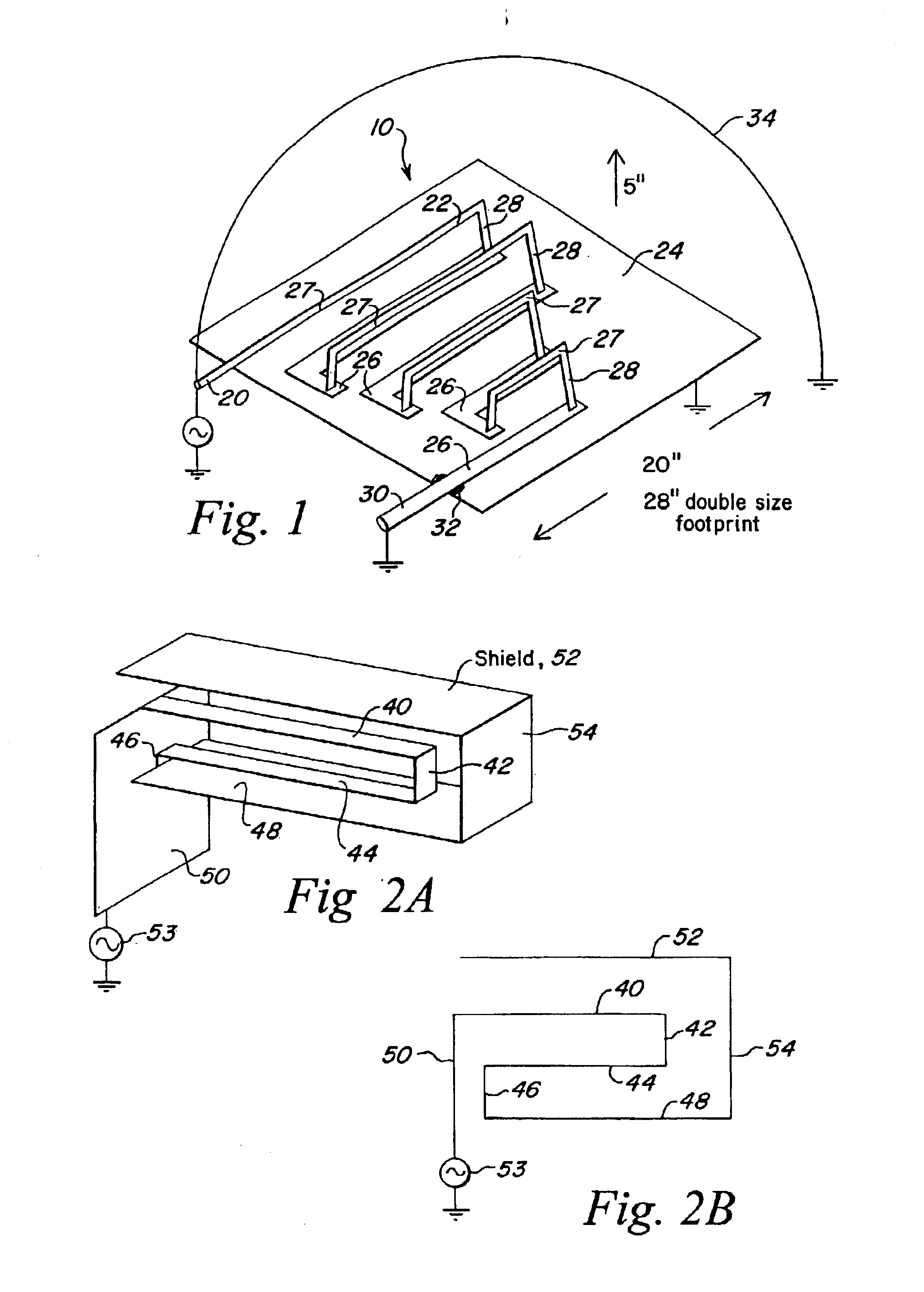
[0044]Referring now to FIG. 1 and as described in U.S. Pat. No. 6,313,716, a slow wave meander line structure 10 is in the form of a folded transmission line 22 mounted on a plate 24. Plate 24 is a conductive plate, with transmission line 22 being optionally constructed from a folded microstrip line that includes alternating sections 26 and 27 which are mounted close to and separated from plate 24, respectively. This variation in height from plate 24 of alternating sections 26 and 27 gives these sections alternating impedance levels with respective to plate 24.

[0045]Sections 26, which are located close to plate 24 to form a lower characteristic impedance are electrically insulated from plate 24 by any suitable means such as an insulating material positioned therebetween. Sections 27 are located at pre-determined distance from plate 24, which predetermined distance determines the characteristic impedance of transmission line section 27 in conjunction with the other physical character...


PUM


Abstract

A standard slow wave meander line having sections of alternating impedance relative to a conductor plate is provided with a top shield connected to the conductor plane for the purpose of lowering the resonant frequency of narrow band antennas and lowering the low frequency cutoff limit of wide band antennas due to a higher delay per unit length occasioned by the use of the top shield. The shielded meander line may be utilized as a coupling device to truncated antennas such as a whip antenna or grounded loop antenna for the purposes of loading the antenna so as to provide lower frequency performance. Since the propagation constant of the meander line structure depends upon the number of high impedance / low impedance transitions per unit length, the utilization of the top shield results in more phase shifts per unit length and thus more delay per unit length, with the symmetric double sided version having double the number of transitions per unit length. When configured to provide a miniature antenna, the utilization of the top shield both lowers the cutoff frequency and eliminates down firing typical of wireless phone antennas due to the ground plane effect. Moreover, the top shield provides a uniform low VSWR over wide bandwidths and by virtue of lowering the operating frequency solves a skip-induced blackout problem due to the lower frequencies that can now be used. Further, for frequency switched meander lines, voltage stress is reduced when using the top shield. Finally, reducing the volume requirement by over 30% permits mobile use where real estate is at a premium.

Description

FIELD OF INVENTION[0001]This invention relates to meander line structures and particularly to the utilization of a top shield.BACKGROUND OF THE INVENTION[0002]Slow wave meander line loaded antennas are known, with the meander line providing for a narrow band and a wide band response, depending on the application. One patent describing such a slow wave meander line structure is U.S. Pat. No. 6,313,716 assigned to the assignee hereof and incorporated herein by reference. In this meander line embodiment, the meander line includes an electrically conductive plate, and a plurality of transmission line sections supported with respect to the conductive plate. The plurality of sections includes a first section loaded relatively closer and parallel to the conductive plate to have a relatively lower characteristic impedance with the conductive plate, and a second section located parallel to and at a relatively greater distance from the conductive plate than the first section to have a relativ...

Claims


Application Information

Patent Timeline
IPC IPC(8): H01P5/02
CPCH01P5/02
Inventor APOSTOLOS, JOHN T.MCKIVERGAN, PATRICK
Owner R A MILLIER IND INC
Learn More